ES4710BD 10 Slots L2/L3/L4 Chassis Switch
An ACL name 1 is set to matching segment 192.168.1.0. QoS was enabled globally, a class map named c1 was created, matching ACL1 in class map; another policy map named p1 was created and refers to c1 in p1, appropriate policies were set to limit bandwidth and burst value. This policy map was applied on Ethernet port 1/2. After the above settings were done, bandwidth for packets from segment 192.168.1.0 through Ethernet port 1/2 is was set to 10 Mbps, with a burst value of 4 MB, all packets exceeding this bandwidth setting in that segment will be dropped.
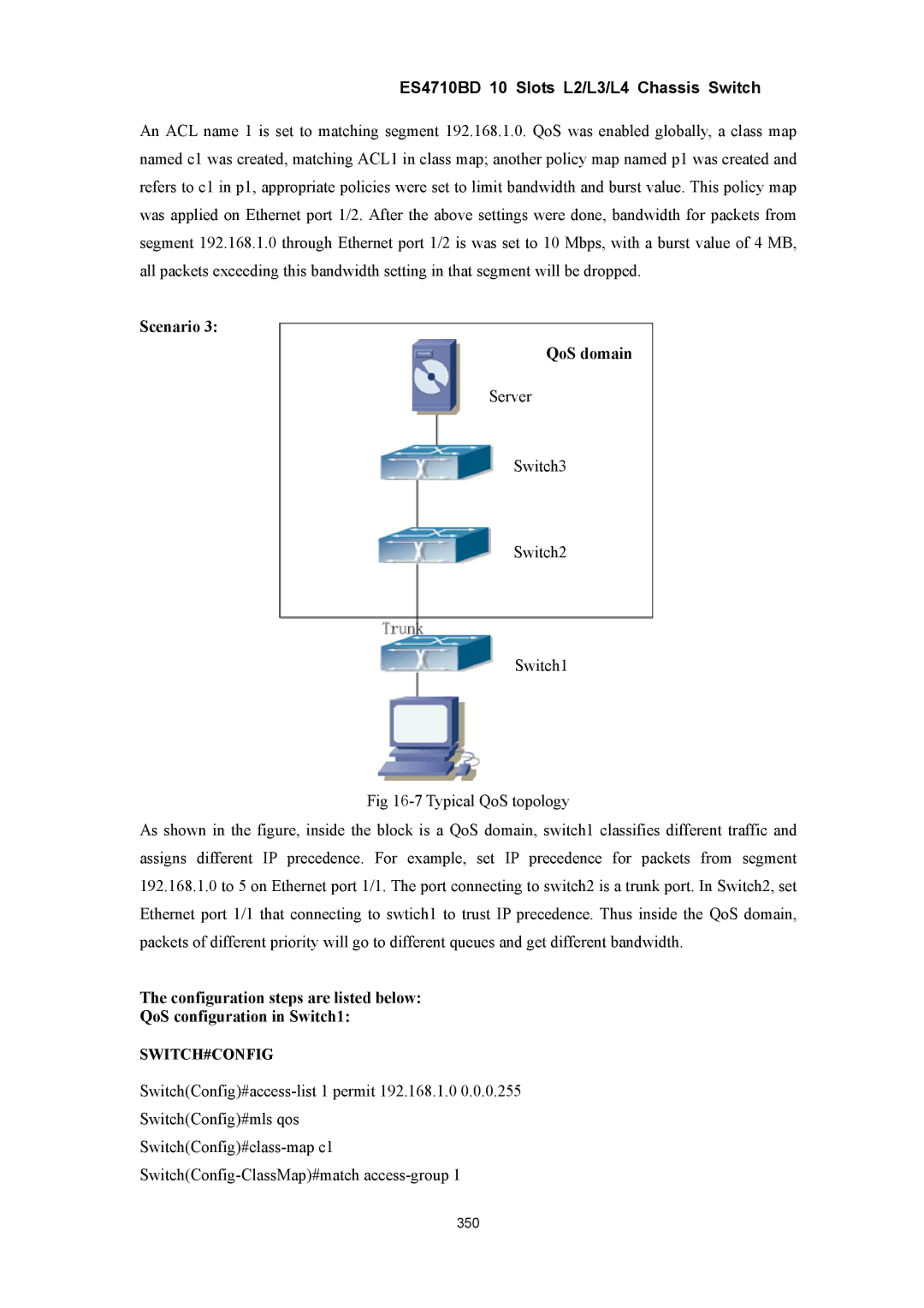
Scenario 3:
QoS domain
Server
Switch3
Switch2
Switch1
Fig
As shown in the figure, inside the block is a QoS domain, switch1 classifies different traffic and assigns different IP precedence. For example, set IP precedence for packets from segment 192.168.1.0 to 5 on Ethernet port 1/1. The port connecting to switch2 is a trunk port. In Switch2, set Ethernet port 1/1 that connecting to swtich1 to trust IP precedence. Thus inside the QoS domain, packets of different priority will go to different queues and get different bandwidth.
The configuration steps are listed below:
QoS configuration in Switch1:
SWITCH#CONFIG
Switch(Config)#mls qos
350