ES4710BD 10 Slots L2/L3/L4 Chassis Switch
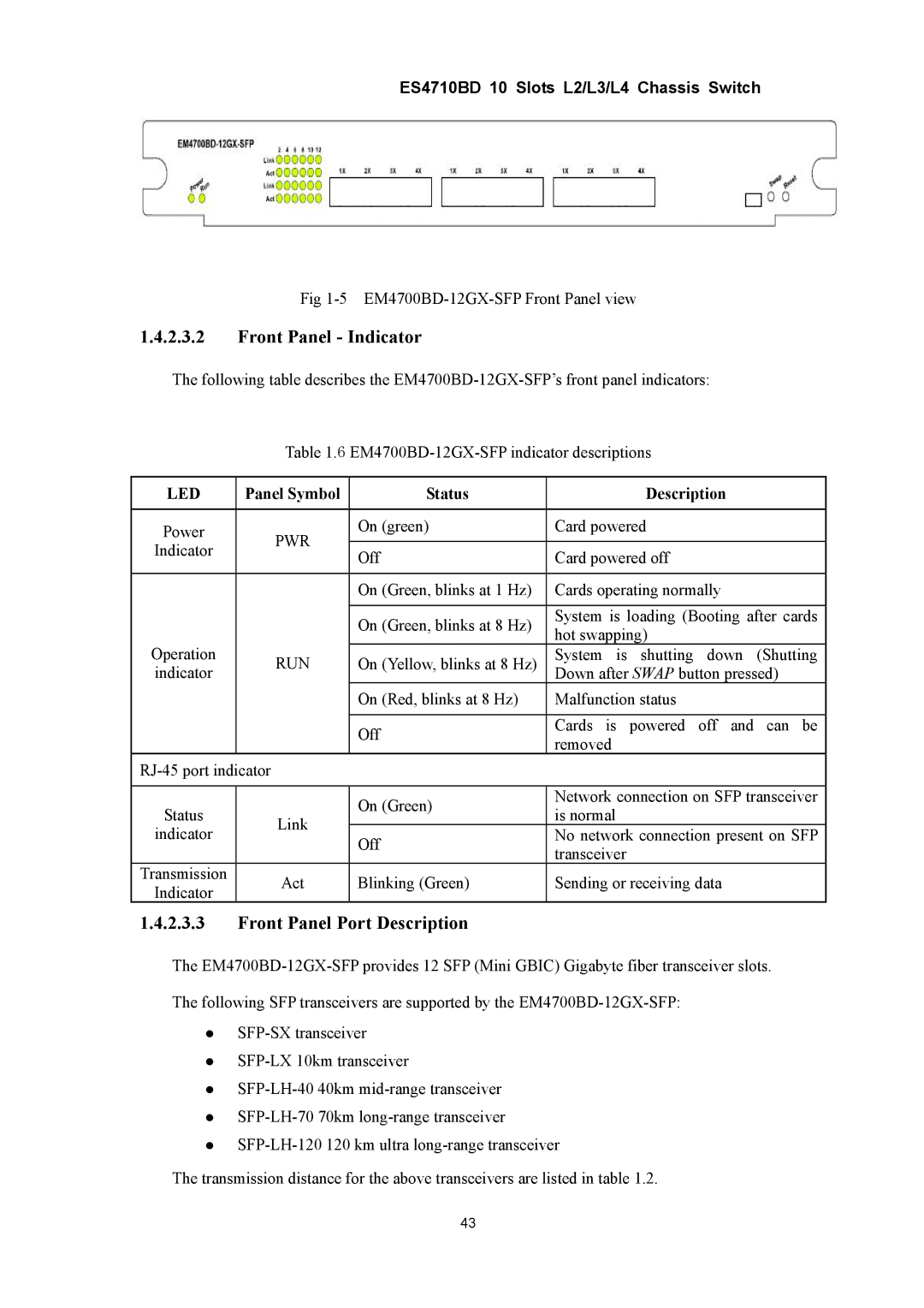
Fig 1-5 EM4700BD-12GX-SFP Front Panel view
1.4.2.3.2Front Panel - Indicator
The following table describes the
Table 1.6
LED | Panel Symbol | Status | Description | |
|
|
|
| |
Power | PWR | On (green) | Card powered | |
|
| |||
Indicator | Off | Card powered off | ||
| ||||
|
| |||
|
|
|
| |
|
| On (Green, blinks at 1 Hz) | Cards operating normally | |
|
|
|
| |
|
| On (Green, blinks at 8 Hz) | System is loading (Booting after cards | |
|
| hot swapping) | ||
Operation |
|
| ||
RUN | On (Yellow, blinks at 8 Hz) | System is shutting down (Shutting | ||
indicator |
|
| Down after SWAP button pressed) | |
|
| On (Red, blinks at 8 Hz) | Malfunction status | |
|
|
|
| |
|
| Off | Cards is powered off and can be | |
|
| removed | ||
|
|
| ||
|
| |||
|
|
|
| |
Status |
| On (Green) | Network connection on SFP transceiver | |
Link | is normal | |||
| ||||
indicator | Off | No network connection present on SFP | ||
| ||||
|
| transceiver | ||
|
|
| ||
Transmission | Act | Blinking (Green) | Sending or receiving data | |
Indicator | ||||
|
|
| ||
1.4.2.3.3Front Panel Port Description
The
z
z
z
z
z
The transmission distance for the above transceivers are listed in table 1.2.
43
