ES4710BD 10 Slots L2/L3/L4 Chassis Switch
PC3£ º10.1.5.2
PC1£ º10.1.1.2 |
|
|
| PC2£ º10.1.4.2 |
|
| vlan3£ 10º .1.5.1 |
| |
| vlan2£10º .1.2.2 | vlan1£ 10º .1.3.2 | ||
vlan1£10º.1.1.1 | vlan2£ 10º .1.2.1 | vlan1£ | 10º .1.3.1 | vlan2£10º.1.4.1 |
|
|
| ||
|
|
| ||
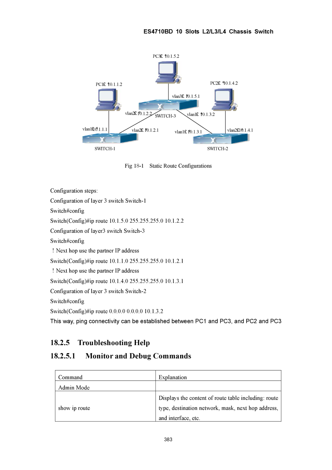
Fig
Configuration steps:
Configuration of layer 3 switch
Switch(Config)#ip route 10.1.5.0 255.255.255.0 10.1.2.2 Configuration of layer3 switch
!Next hop use the partner IP address Switch(Config)#ip route 10.1.1.0 255.255.255.0 10.1.2.1 !Next hop use the partner IP address Switch(Config)#ip route 10.1.4.0 255.255.255.0 10.1.3.1 Configuration of layer 3 switch
Switch(Config)#ip route 0.0.0.0 0.0.0.0 10.1.3.2
This way, ping connectivity can be established between PC1 and PC3, and PC2 and PC3
18.2.5Troubleshooting Help
18.2.5.1Monitor and Debug Commands
Command | Explanation |
Admin Mode |
|
| Displays the content of route table including: route |
show ip route | type, destination network, mask, next hop address, |
| and interface, etc. |
| 383 |