Cisco Systems OL-6256-17 manual Inlet Grille-Modular Configuration Power Supply

Models: OL-6256-17

1 182
Download 182 pages 23.48 Kb
Page 167
Image 167

Chapter 5 Installing and Removing Exterior Components

Installing or Removing the Front Side Exterior Components

Installing the Inlet Grille—Modular Configuration Power Supply

This section describes how to install the inlet grille on a Cisco CRS 8-slot line card chassis with a modular configuration power supply installed. The grille covers the power module and air intake areas at the bottom of the front (PLIM) side of the chassis, just below the card cage. Figure 5-4shows the inlet grille that can be installed on a Cisco CRS 8-slot line card chassis with a modular configuration power supply.

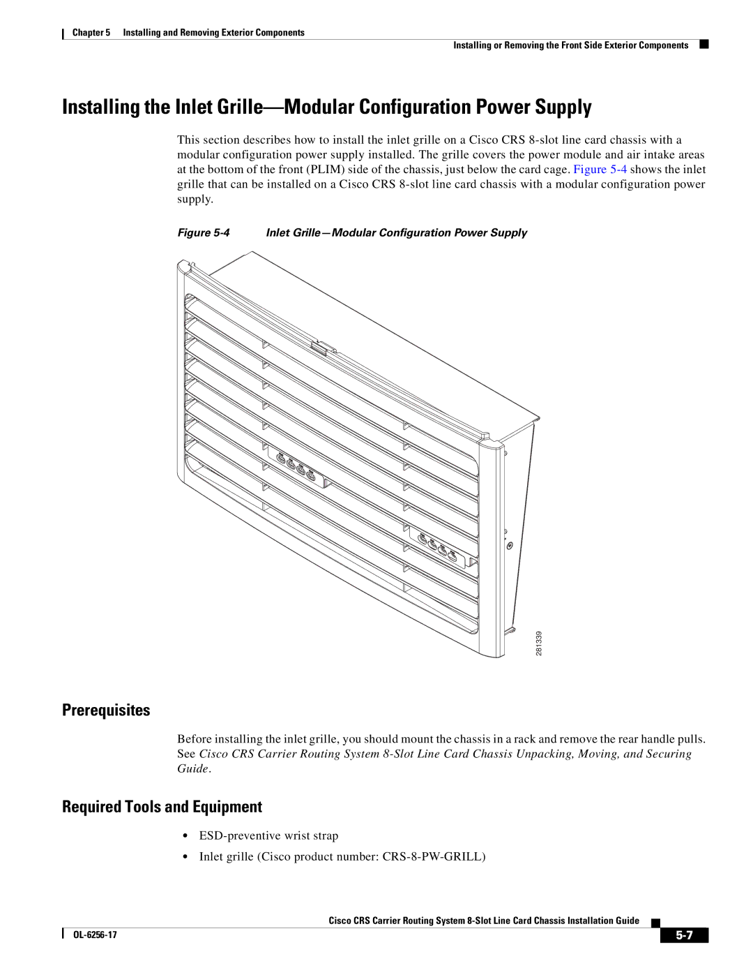
Figure 5-4 Inlet Grille—Modular Configuration Power Supply

281339

Prerequisites

Before installing the inlet grille, you should mount the chassis in a rack and remove the rear handle pulls. See Cisco CRS Carrier Routing System 8-Slot Line Card Chassis Unpacking, Moving, and Securing Guide.

Required Tools and Equipment

ESD-preventive wrist strap

Inlet grille (Cisco product number: CRS-8-PW-GRILL)

Cisco CRS Carrier Routing System 8-Slot Line Card Chassis Installation Guide


OL-6256-17

5-7


Page 167
Image 167
Cisco Systems OL-6256-17 manual Inlet Grille-Modular Configuration Power Supply