Chapter 2 Installing and Removing Power Components
How to Install or Remove Modular Configuration Power Components
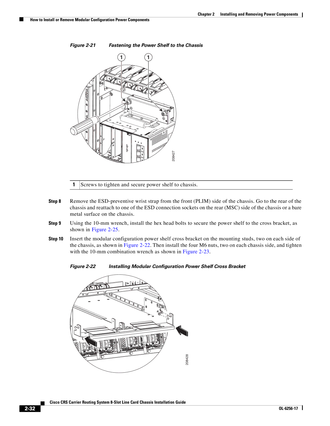
Figure 2-21 Fastening the Power Shelf to the Chassis
1 1
208427
1
Screws to tighten and secure power shelf to chassis.
Step 8 Remove the
Step 9 Using the
Step 10 Insert the modular configuration power shelf cross bracket on the mounting studs, two on each side of the chassis, as shown in Figure
Figure 2-22 Installing Modular Configuration Power Shelf Cross Bracket
208428
Cisco CRS Carrier Routing System
|
| |
|