Chapter 5 Installing and Removing Exterior Components
Installing or Removing the Front Side Exterior Components
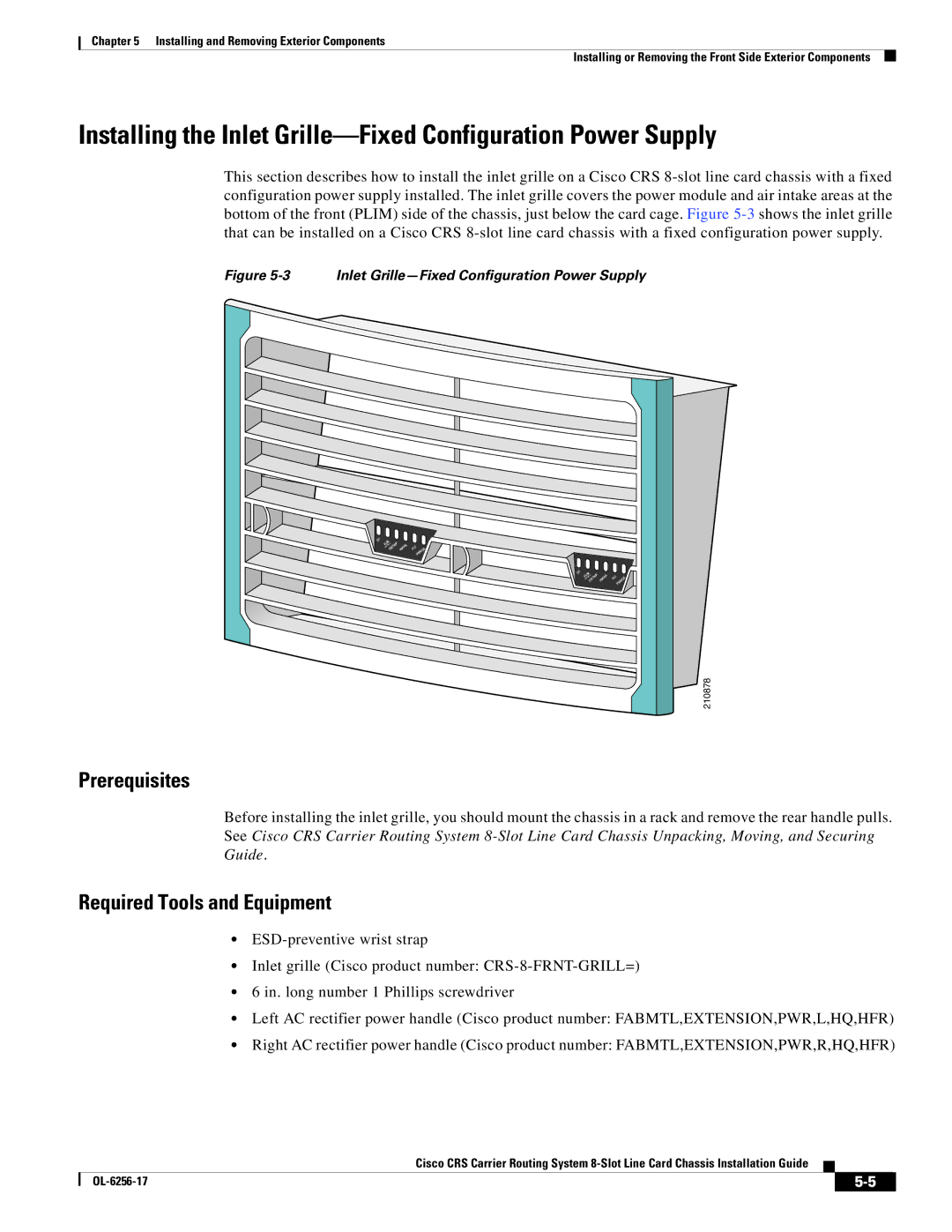
Installing the Inlet Grille—Fixed Configuration Power Supply
This section describes how to install the inlet grille on a Cisco CRS
Figure 5-3 Inlet Grille—Fixed Configuration Power Supply
OT | I/LIM |
|
|
|
|
| |
| CB/TRIP IN/FAIL | FLT | K |
|
|
| R/O |
|
|
| PW |
OT | I/LIM |
|
|
| |
| CB/TRIP IN/FAIL | FLT |
|
| PWR/OK |
210878
Prerequisites
Before installing the inlet grille, you should mount the chassis in a rack and remove the rear handle pulls. See Cisco CRS Carrier Routing System
Required Tools and Equipment
•
•Inlet grille (Cisco product number:
•6 in. long number 1 Phillips screwdriver
•Left AC rectifier power handle (Cisco product number: FABMTL,EXTENSION,PWR,L,HQ,HFR)
•Right AC rectifier power handle (Cisco product number: FABMTL,EXTENSION,PWR,R,HQ,HFR)
Cisco CRS Carrier Routing System
|
| ||
|
|