Chapter 4 Installing and Removing Line Cards, PLIMs, and Associated Components
How to Install or Remove an RP, PRP, or DRP PLIM
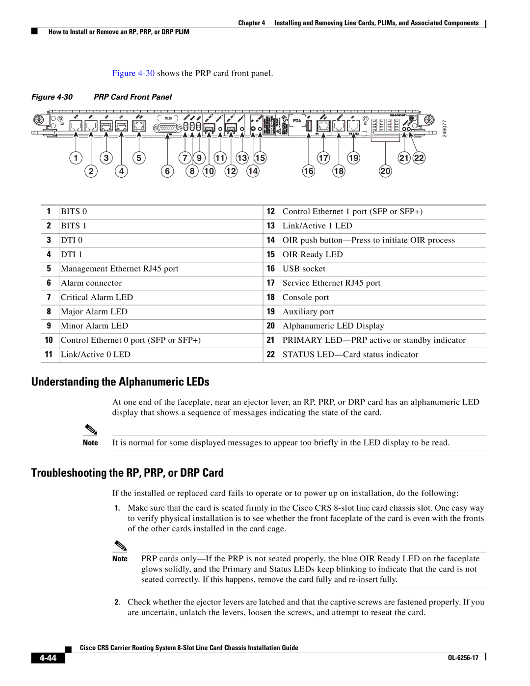
Figure 4-30 shows the PRP card front panel.
Figure | PRP Card Front Panel |
|
|
|
|
|
|
|
|
| |
|
|
|
|
|
|
|
|
|
|
| 246077 |
1 | 3 | 5 | 7 | 9 | 11 | 13 | 15 | 17 | 19 | 21 | 22 |
2 | 4 | 6 | 8 | 10 | 12 |
| 14 | 16 | 18 | 20 |
|
1 | BITS 0 | 12 | Control Ethernet 1 port (SFP or SFP+) |
|
|
|
|
2 | BITS 1 | 13 | Link/Active 1 LED |
|
|
|
|
3 | DTI 0 | 14 | OIR push |
|
|
|
|
4 | DTI 1 | 15 | OIR Ready LED |
|
|
|
|
5 | Management Ethernet RJ45 port | 16 | USB socket |
|
|
|
|
6 | Alarm connector | 17 | Service Ethernet RJ45 port |
|
|
|
|
7 | Critical Alarm LED | 18 | Console port |
|
|
|
|
8 | Major Alarm LED | 19 | Auxiliary port |
|
|
|
|
9 | Minor Alarm LED | 20 | Alphanumeric LED Display |
|
|
|
|
10 | Control Ethernet 0 port (SFP or SFP+) | 21 | PRIMARY |
|
|
|
|
11 | Link/Active 0 LED | 22 | STATUS |
|
|
|
|
Understanding the Alphanumeric LEDs
At one end of the faceplate, near an ejector lever, an RP, PRP, or DRP card has an alphanumeric LED display that shows a sequence of messages indicating the state of the card.
Note It is normal for some displayed messages to appear too briefly in the LED display to be read.
Troubleshooting the RP, PRP, or DRP Card
If the installed or replaced card fails to operate or to power up on installation, do the following:
1.Make sure that the card is seated firmly in the Cisco CRS
Note PRP cards
2.Check whether the ejector levers are latched and that the captive screws are fastened properly. If you are uncertain, unlatch the levers, loosen the screws, and attempt to reseat the card.
Cisco CRS Carrier Routing System
|
| |
|