Chapter 2 Installing and Removing Power Components
How to Install or Remove Modular Configuration Power Components
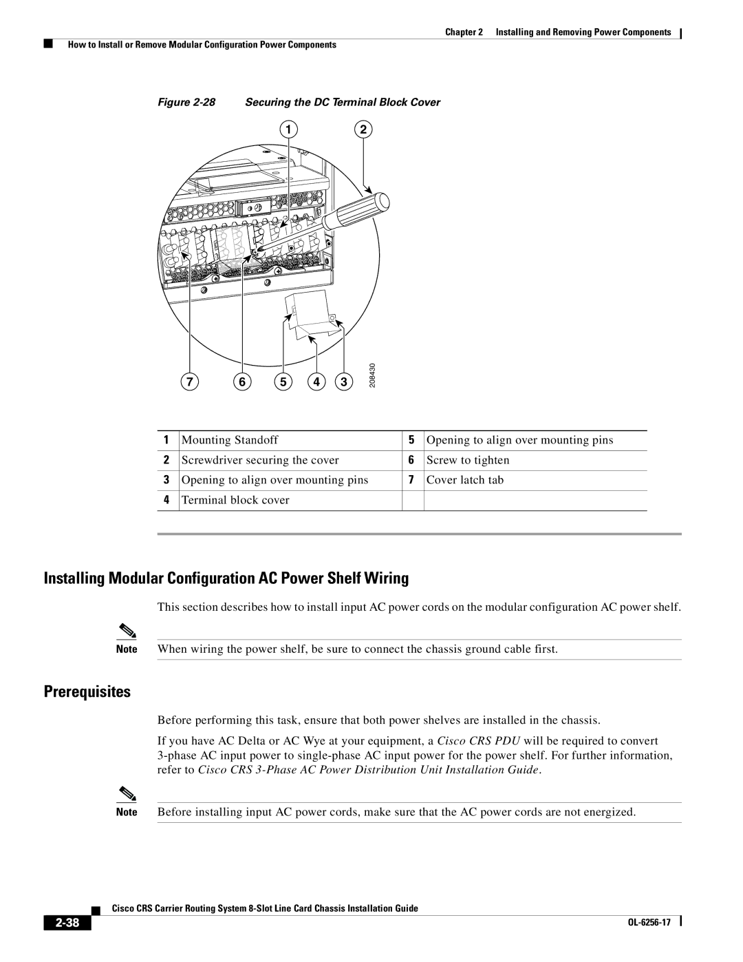
Figure 2-28 Securing the DC Terminal Block Cover
12
7 | 6 | 5 | 4 | 3 |
208430
1 | Mounting Standoff | 5 | Opening to align over mounting pins |
|
|
|
|
|
|
2 | Screwdriver securing the cover | 6 | Screw to tighten | |
|
|
|
|
|
3 | Opening to align over mounting pins | 7 | Cover latch tab | |
|
|
|
|
|
4 | Terminal block cover |
|
|
|
|
|
|
|
|
|
|
|
|
|
Installing Modular Configuration AC Power Shelf Wiring
This section describes how to install input AC power cords on the modular configuration AC power shelf.
Note When wiring the power shelf, be sure to connect the chassis ground cable first.
Prerequisites
Before performing this task, ensure that both power shelves are installed in the chassis.
If you have AC Delta or AC Wye at your equipment, a Cisco CRS PDU will be required to convert
Note Before installing input AC power cords, make sure that the AC power cords are not energized.
Cisco CRS Carrier Routing System
|
| |
|