Advanced Digital Information Corporation | FastStor 1 | |
|
|
|
Step 4. Removing the Transport Lock
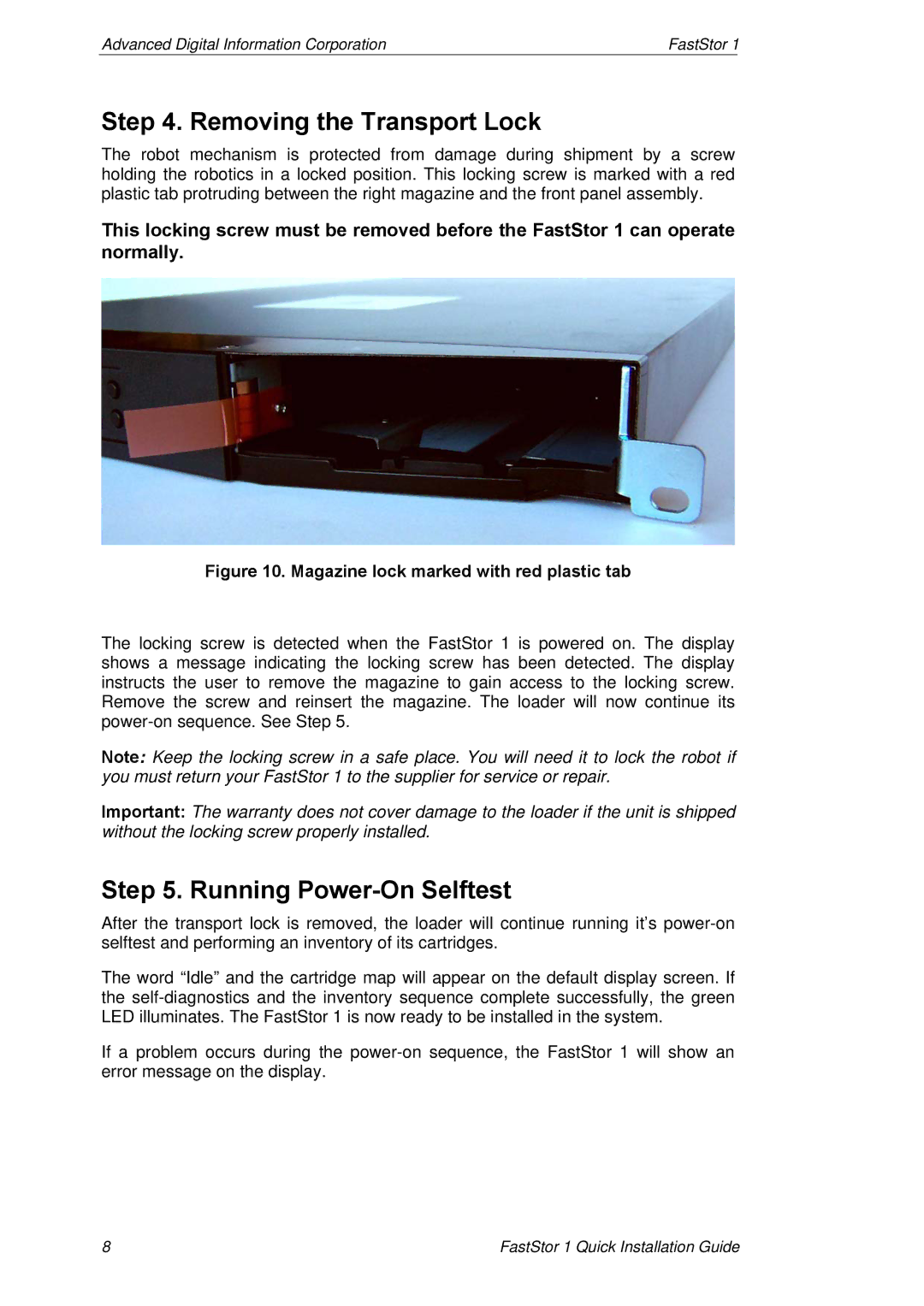
The robot mechanism is protected from damage during shipment by a screw holding the robotics in a locked position. This locking screw is marked with a red plastic tab protruding between the right magazine and the front panel assembly.
This locking screw must be removed before the FastStor 1 can operate normally.
Figure 10. Magazine lock marked with red plastic tab
The locking screw is detected when the FastStor 1 is powered on. The display shows a message indicating the locking screw has been detected. The display instructs the user to remove the magazine to gain access to the locking screw. Remove the screw and reinsert the magazine. The loader will now continue its
Note: Keep the locking screw in a safe place. You will need it to lock the robot if you must return your FastStor 1 to the supplier for service or repair.
Important: The warranty does not cover damage to the loader if the unit is shipped without the locking screw properly installed.
Step 5. Running Power-On Selftest
After the transport lock is removed, the loader will continue running it’s
The word “Idle” and the cartridge map will appear on the default display screen. If the
If a problem occurs during the
8 | FastStor 1 Quick Installation Guide |