Installation instructions
5.Installation of Mounting Brackets and First Sealing Strip
NOTE: Windows come in a variety of different styles. Therefore, it may be necessary to modify or improve your particular installation.
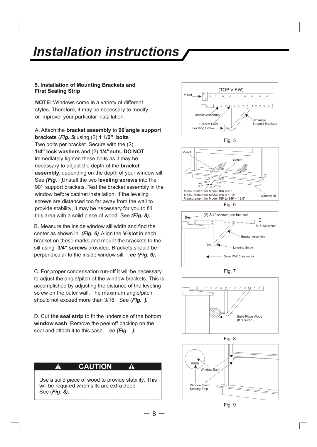
A. Attach the bracket assembly to 90 angle support brackets (Fig. 5) using (2) 1 1/2" bolts
Two bolts per bracket. Secure with the (2) 1/4" lock washers and (2) 1/4"nuts. DO NOT immediately tighten these bolts as it may be necessary to adjust the depth of the bracket assembly, depending on the depth of your window sill. See (Fig. 7).Install the two leveling screws into the
90support brackets. Test the bracket assembly in the window before cabinet installation. If the leveling screws are distanced too far away from the wall to provide stability, it may be necessary for you to fill this area with a solid piece of wood. See (Fig. 8).
B.Measure the inside window sill width and find the center as shown in (Fig. 6). Align the
C.For proper condensation
D.Cut the seal strip to fit the underside of the bottom
window sash. Remove the
! CAUTION !
Use a solid piece of wood to provide stability. This will be required when sills are extra deep.
See (Fig. 8).
(TOP VIEW) |
|
| |
Bracket Assembly |
|
| 90 Angle |
Bracket Bolts | Support Brackets |
Leveling Screw |
|
Fig. 5
Center
9.6" 9.6"
10.3"
10.3"
12.6" ![]() 12.6"
12.6"
Measurement for Model 10K =9.6"
Measurement for Model 12K = 10.3"Window sill Measurement for Model 18K to 24K = 12.6"
Fig. 6
(2) 3/4" screws per bracket |
3/16" Maximum |
Bracket Assembly |
Leveling Screw |
Outer Wall Construction |
Fig. 7
Solid Piece Wood |
(If required) |
Fig. 8
Window Sash |
Window Sash |
Sealing Strip |
Fig. 9
8