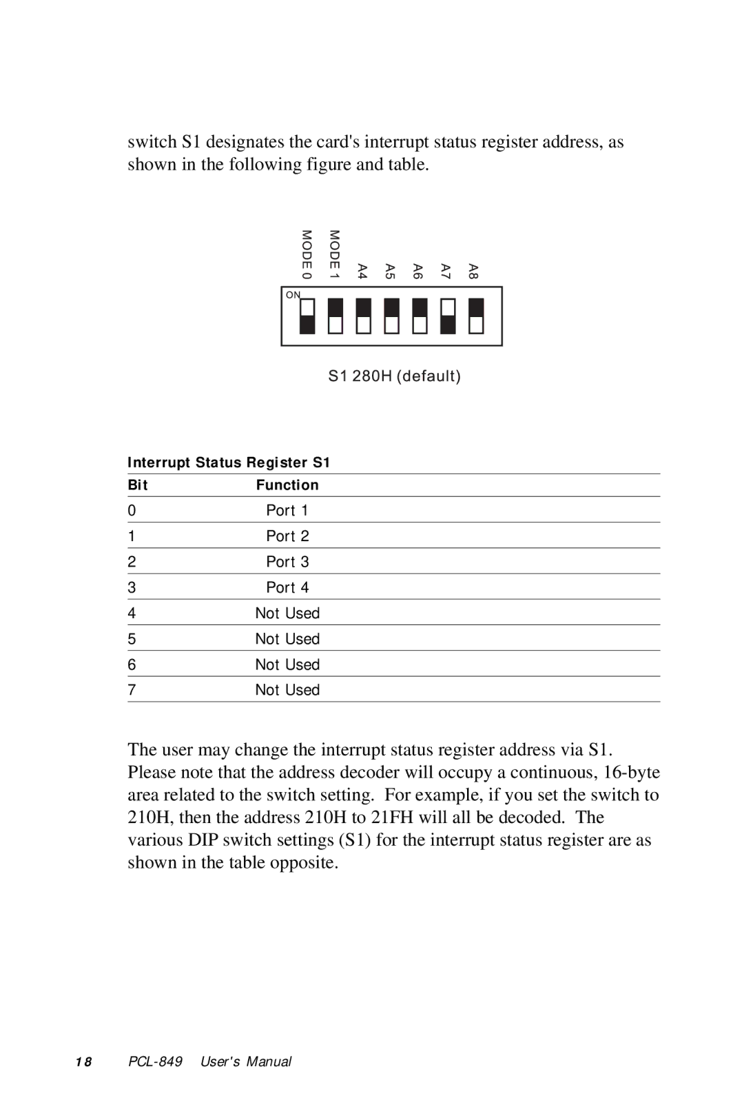
switch S1 designates the card's interrupt status register address, as shown in the following figure and table.
Interrupt Status Register S1
Bit | Function |
0 | Port 1 |
1 | Port 2 |
2 | Port 3 |
|
|
3 | Port 4 |
|
|
4 | Not Used |
|
|
5 | Not Used |
6 | Not Used |
7 | Not Used |
The user may change the interrupt status register address via S1. Please note that the address decoder will occupy a continuous,
1 8 |
