3.1Introduction
The
3.2Connections to Standard LCDs
The following tables illustrate typical LCD connection pinouts for the
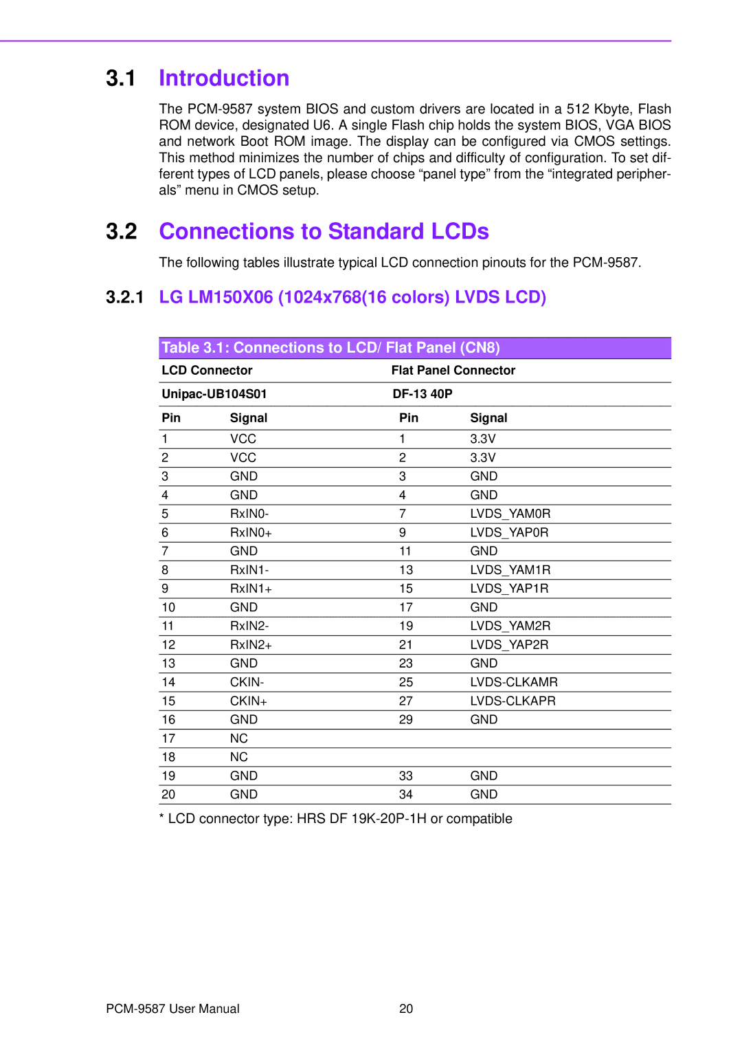
3.2.1LG LM150X06 (1024x768(16 colors) LVDS LCD)
Table 3.1: Connections to LCD/ Flat Panel (CN8)
LCD Connector | Flat Panel Connector | ||
|
|
| |
| |||
|
|
|
|
Pin | Signal | Pin | Signal |
|
|
|
|
1 | VCC | 1 | 3.3V |
2 | VCC | 2 | 3.3V |
3 | GND | 3 | GND |
4 | GND | 4 | GND |
5 | RxIN0- | 7 | LVDS_YAM0R |
6 | RxIN0+ | 9 | LVDS_YAP0R |
7 | GND | 11 | GND |
8 | RxIN1- | 13 | LVDS_YAM1R |
9 | RxIN1+ | 15 | LVDS_YAP1R |
10 | GND | 17 | GND |
11 | RxIN2- | 19 | LVDS_YAM2R |
12 | RxIN2+ | 21 | LVDS_YAP2R |
13 | GND | 23 | GND |
14 | CKIN- | 25 | |
15 | CKIN+ | 27 | |
16 | GND | 29 | GND |
17NC
18NC
19 | GND | 33 | GND |
20 | GND | 34 | GND |
* LCD connector type: HRS DF
20 |