2.17.3DVI LCD panel connector(CN9)
Digital Visual Interface (DVI) is the standard interface for
Panel type and Resolution mode selection
Customer can select display type and boot number from BIOS menu selection.
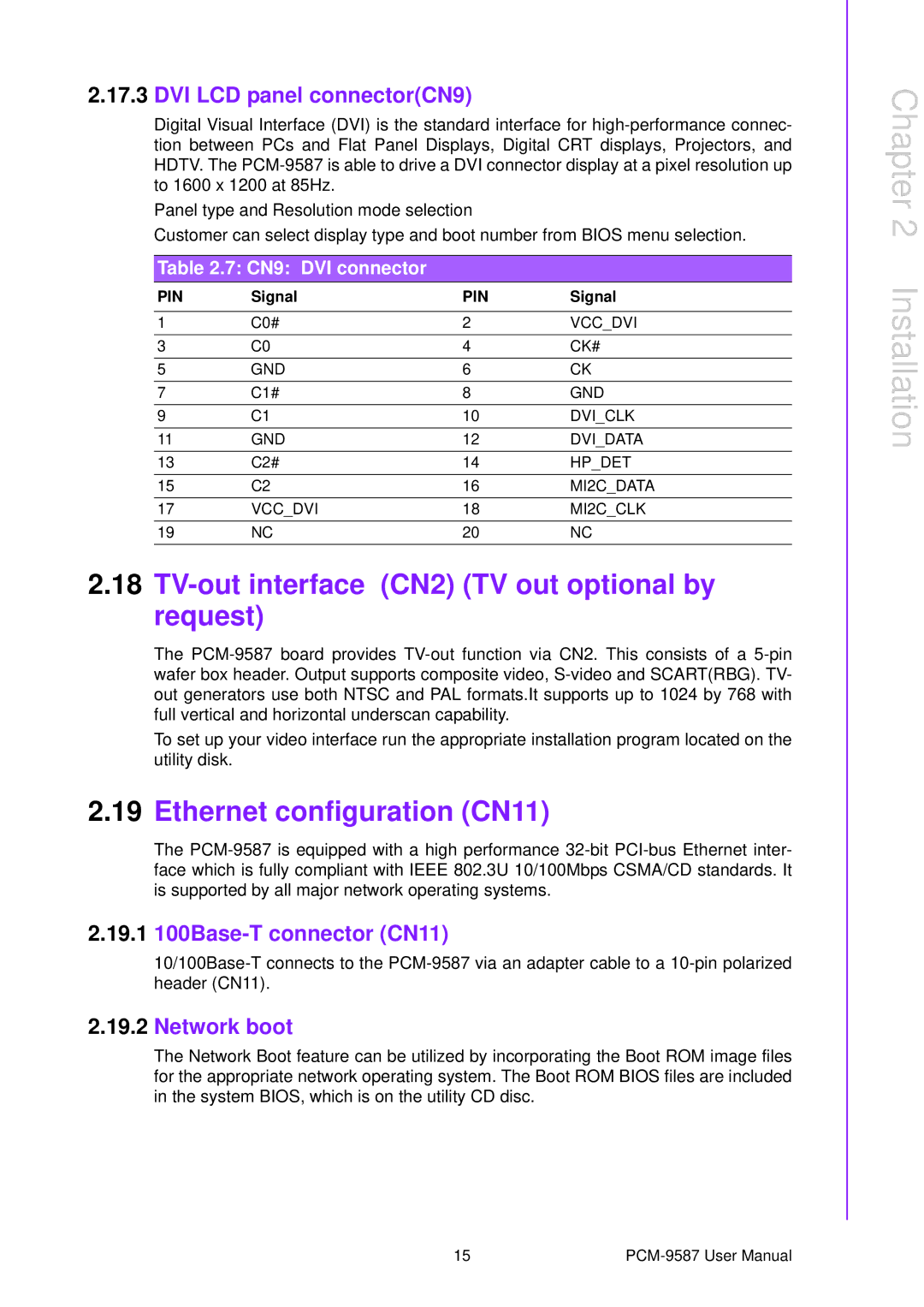
Table 2.7: CN9: DVI connector
PIN | Signal | PIN | Signal |
|
|
|
|
1 | C0# | 2 | VCC_DVI |
3 | C0 | 4 | CK# |
5 | GND | 6 | CK |
7 | C1# | 8 | GND |
9 | C1 | 10 | DVI_CLK |
11 | GND | 12 | DVI_DATA |
13 | C2# | 14 | HP_DET |
15 | C2 | 16 | MI2C_DATA |
17 | VCC_DVI | 18 | MI2C_CLK |
19 | NC | 20 | NC |
2.18TV-out interface (CN2) (TV out optional by request)
The
To set up your video interface run the appropriate installation program located on the utility disk.
2.19Ethernet configuration (CN11)
The
2.19.1100Base-T connector (CN11)
2.19.2Network boot
The Network Boot feature can be utilized by incorporating the Boot ROM image files for the appropriate network operating system. The Boot ROM BIOS files are included in the system BIOS, which is on the utility CD disc.
Chapter 2 Installation
15 |