2.20USB connectors (CN18,CN20)

The PCM-9587 board provides up to four USB (Universal Serial Bus) 2.0 ports. This gives complete Plug and Play, and hot attach/detach for up to 127 external devices. The USB interfaces comply with USB specification Rev. 1.1, and are fuse protected.

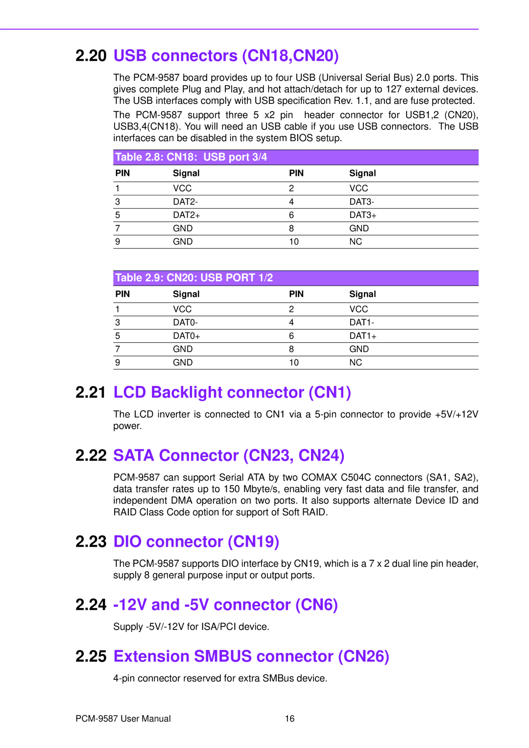
The PCM-9587 support three 5 x2 pin header connector for USB1,2 (CN20), USB3,4(CN18). You will need an USB cable if you use USB connectors. The USB interfaces can be disabled in the system BIOS setup.

Table 2.8: CN18: USB port 3/4

PIN

Signal

PIN

Signal


1

VCC

2

VCC

3

DAT2-

4

DAT3-

5

DAT2+

6

DAT3+

7

GND

8

GND

9

GND

10

NC

Table 2.9: CN20: USB PORT 1/2

PIN

Signal

PIN

Signal


1

VCC

2

VCC

3

DAT0-

4

DAT1-

5

DAT0+

6

DAT1+

7

GND

8

GND

9

GND

10

NC

2.21LCD Backlight connector (CN1)

The LCD inverter is connected to CN1 via a 5-pin connector to provide +5V/+12V power.

2.22SATA Connector (CN23, CN24)

PCM-9587 can support Serial ATA by two COMAX C504C connectors (SA1, SA2), data transfer rates up to 150 Mbyte/s, enabling very fast data and file transfer, and independent DMA operation on two ports. It also supports alternate Device ID and RAID Class Code option for support of Soft RAID.

2.23DIO connector (CN19)

The PCM-9587 supports DIO interface by CN19, which is a 7 x 2 dual line pin header, supply 8 general purpose input or output ports.

2.24-12V and -5V connector (CN6)

Supply -5V/-12V for ISA/PCI device.

2.25Extension SMBUS connector (CN26)

4-pin connector reserved for extra SMBus device.

PCM-9587 User Manual

16

Page 24
Image 24
Advantech PCM-9587 USB connectors CN18,CN20, LCD Backlight connector CN1, Sata Connector CN23, CN24, DIO connector CN19