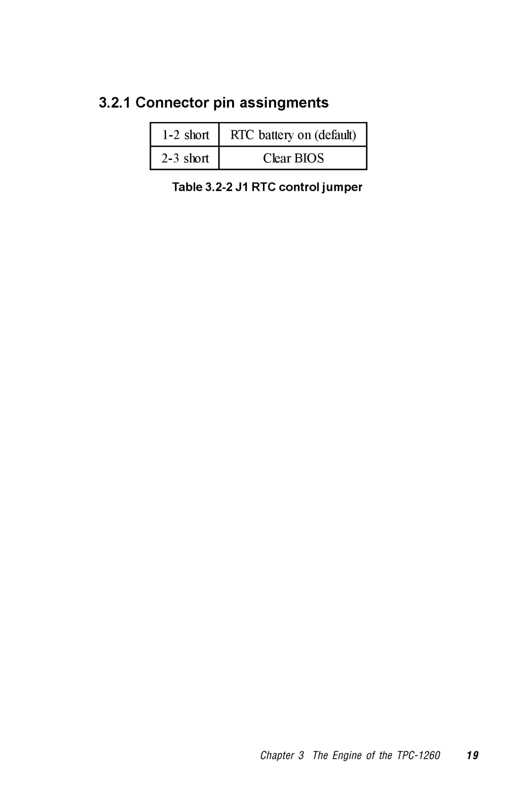
Manuals
/
Advantech
/
Computer Equipment
/
Computer Monitor
Advantech
TPC-1260 manual Connector pin assingments, short, RTC battery on default, Clear BIOS
Models:
TPC-1260
1
29
74
74
Download
74 pages
53.49 Kb
26
27
28
29
30
31
32
33
<
>
Specifications
Install
Exploded diagram
CPU board replacement
Dimension
Maintenance
command will overwrite all registry data-not only the
RTC battery on default
Appendix A Watchdog Timer
System Tuning
Page 29
Image 29
3.2.1 Connector pin assingments
1-2
short
RTC battery on (default)
2-3
short
Clear BIOS
Table
3.2-2
J1 RTC control jumper
Chapter 3 The Engine of the
TPC-1260
1 9
Page 28
Page 30
Page 29
Image 29
Page 28
Page 30
Contents
Users Manual
TPC-1260
1st edition May
Copyright notice
Acknowledgments
Packing List
FCC Class A
Safety Instructions
Wichtige Sicherheishinweise
Chapter 5 System Tuning
Contents
Chapter 6 Maintenance
Chapter 1 General Information
Watchdog Timer Programming Example
Appendix A Serial Port Settings
Windows 2000 Touch Screen Installation
Appendix D Fuse Specifications
Tables
Page
Sections include Introduction Specifications LCD Specifications
General Information
Touchscreen specifications Power I/O ports Mounting Exploded diagram
Dimensions and cutout
1.1 Introduction
1.2.2 I/O ports
1.2 Specifications
1.1.3 Storage
1.1.4 Safety and environment
Safety
Environment
There might be several bright or dark pixels on the
1.3 LCD specifications
LCD. This comes from the production of the LCD
Such phenomenon is claimed to be normal according
1.6 I/O ports arrangement
1.4 Touchscreen specifications
1.5 Power
1.7.1 Panel mounting
1.7 Mounting
8 TPC-1260 Users Manual
1.7.2 Wall mounting/desktop stand
Chapter 1 General Information
1.8 Exploded diagram
Figure 1.8-1Exploded diagram
Weight 2.2 kg without HDD Dimension 311 x 237 x 50 mm WxHxD
1.9 Dimensions and cutout
Figure 1.9-1 Dimensions and cutout
Cutout 302 x 228 mm suggested
System Quick Starting
1 2 TPC-1260 Users Manual
Figure 2-1 Unpack the package
Chapter 2 Quick Start Guide
Figure 2-2 Install HDD
1 4 TPC-1260 Users Manual
Figure 2-3 Install CompactFlash memory card
Figure 2-4 Power connector and power lines
Figure 2-5 Power connector pin assignment
Step 4 Plug the power lines to the system power receptor
Figure 2-6 Plug the power lines to the system power receptor
Chapter 2 Quick Start Guide
Figure 2-7 Turn on power switch
Step 5 Turn on the system power switch
the main boards and the I/O boards
The Engine of the TPC-1260
The operating engine of the TPC-1260 is composed of two PC boards
3.2 CPC-2365 main board
3.1 Introduction
Label
Function
RTC battery on default
3.2.1 Connector pin assingments
Clear BIOS
1-2 short
2 0 TPC-1260 Users Manual
3.3 TPC-1260 I/O board
Figure 3.3-1 TPC-1260 I/O board I/O port side
Chapter 3 The Engine of the TPC-1260
Figure 3.3-2 TPC-1260 I/O board LCD side
Label
Table 3.3-1 TPC-1260 I/O board connector/jumper list
Function
2 2 TPC-1260 Users Manual
C H A P T E R
Windows CE in the TPC-1260
Figure 4.1-1 Windows CE on TPC-1260
4.1 Introduction
4.2.2 Screen saver
4.2 TPC-1260 utilities
4.2.1 Soft-keyboard
Please be careful when selecting “Save”. This
4.2.3 Watchdog timer
command will overwrite all registry data-not only the
screen saving settings
4.3.1 Networking via Ethernet
4.3 Networking
Figure 4.3-1 Control Panel
Chapter 4 Windows CE in the TPC-1260
Step 2 Double click “Communications”
4.3.2 Networking via serial port
3 2 TPC-1260 Users Manual
Figure 4.3-4 Make new connection Figure 4.3-5 Direct connection
Chapter 4 Windows CE in the TPC-1260
Figure 4.3-6 Default settings Figure 4.3-7 Default settings continued
4.4.1 System requirements
4.4 Application program development
4.3.3 Web browser
4.4.2 Building Windows CE runtime
3 6 TPC-1260 Users Manual
C H A P T E R
System Tuning
5.1 LCD brightness tuning
5.1 LCD contrast tuning
5.2.2 Windows CE
5.2 Touchscreen calibration
5.2.1 DOS/Windows Family
Step 3 Double-click “Control Panel”
Step 2 Double-click “Windows Explorer”
Figure 5.2-2 Windows Explorer
Figure 5.2-3Control Panel
Figure 5.2-5 Double-tap calibration
Figure 5.2-4 Calibration
Step 9 When calibration is done the utility will save the settings
Chapter 5 System Tune Up
4 4 TPC-1260 Users Manual
C H A P T E R
Maintenance
6.1 CPU board replacement
Step 7 Insert a new CPU board to the SO-DIMM connector
Step 1 Remove the fuse cover
6.2 Fuse replacement
Step 2 Replace the damaged fuse with a new one
Step 3 Replace the fuse cover
Serial Port Settings
A.1 Baud Rate Settings SW1
Serial Port Settings
= Off *= Default
= On
= Off *= Default
A.2 Data Format/RS-422 Control Settings
Appendix A Watchdog Timer
= On
5 2 TPC-642 Users Manual
Watchdog Timer Programming Example
Step 2 clear the watchdog timer
B.1 Watchdog timer programming example
the utility to enable/disable the watchdog timer under
Windows CE is built in the Advantech Windows CE
Windows Touch Screen Installation
Figure C-1 Hardware
C.1 Touchscreen driver in Windows
Appendix C Windows
Step 3 Click the Device Manager… button
Figure C-2 Device manager
5 8 TPC-1260 Users Manual
Figure C-3 Uninstall the driver
Appendix C Windows
Figure C-4 Mouse properties
6 0 TPC-1260 Users Manual
Step 6 Go to the Driver page, and click the Update Driver button
Figure C-5 Update driver
Appendix C Windows
Figure C-6 Select driver from known list
6 2 TPC-1260 Users Manual
Step 8 In the Manufacturers list, find out and select Touch- Screen
Figure C-7 Find out TouchScreen in the manufacturers list
Appendix C Windows
Figure C-8 Re-install the driver
6 4 TPC-1260 Users Manual
Figure C-9 Finish installation of touchscreen driver
Fuse Specifications
The fuse used on the TPC-1260 is
D. Fuse Specifications
The fuse is set to break as the input voltage exceeds
33 VDC for your protection