Manuals
/
Advantech
/
Computer Equipment
/
Computer Monitor
Advantech
TPC-1260
manual
Data Format/RS-422 Control Settings
Models:
TPC-1260
1
59
74
74
Download
74 pages
53.49 Kb
56
57
58
59
60
61
62
63
Specifications
Install
Exploded diagram
Default settings
Watchdog timer
Dimension
Maintenance
Connector pin assingments
System Tuning
Serial Port Settings
Page 59
Image 59
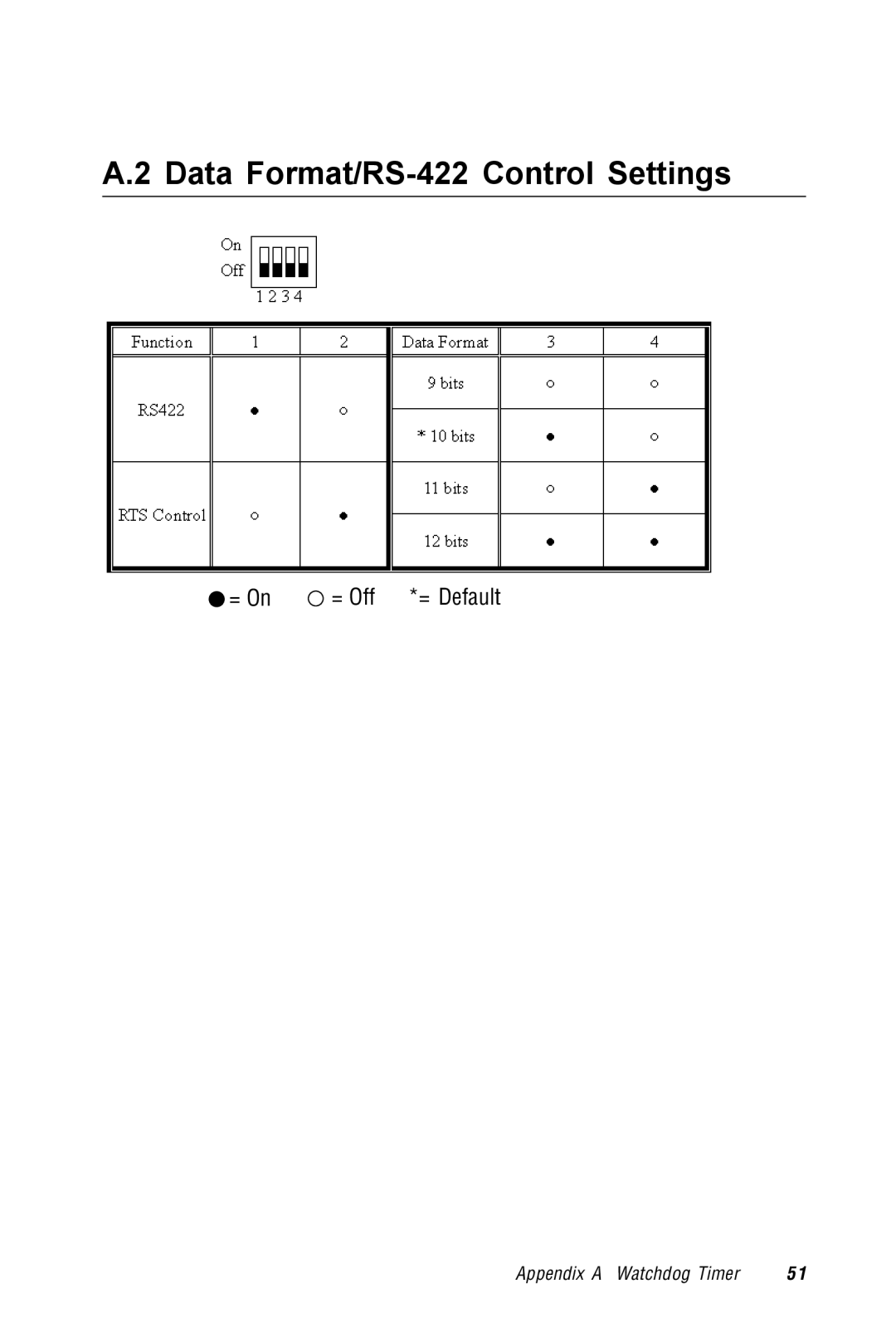
A.2 Data
Format/RS-422
Control Settings
= On
= Off *= Default
Appendix A Watchdog Timer
5 1
Page 58
Page 60
Page 59
Image 59
Page 58
Page 60
Contents
TPC-1260
Copyright notice Acknowledgments
Packing List
FCC Class a
Safety Instructions
Wichtige Sicherheishinweise
Contents
Figures
Tables
Page
General Information
Introduction
2 I/O ports
Specifications
Storage
Safety and environment
LCD Mtbf
LCD specifications
I/O ports arrangement
Touchscreen specifications
Power
Panel mounting
Mounting
Wall mounting/desktop stand
1Exploded diagram
Exploded diagram
1 Dimensions and cutout
Dimensions and cutout
System Quick Starting
Unpack the package
Install HDD
Install CompactFlash memory card
Plug the power lines to the system power receptor
Turn on the system power switch
Engine of the TPC-1260
Label Function
CPC-2365 main board
Connector pin assingments
1 TPC-1260 I/O board I/O port side
TPC-1260 I/O board
2 TPC-1260 I/O board LCD side
1 TPC-1260 I/O board connector/jumper list
Windows CE in the TPC-1260
1 Windows CE on TPC-1260
Screen saver
TPC-1260 utilities
Soft-keyboard
2 Screen saver setting
Watchdog timer
Networking via Ethernet
Networking
2 Neworking by Windows Explorer
3 Remote networking
Networking via serial port
4 Make new connection
6 Default settings
System requirements
Application program development
Web browser
Building Windows CE runtime
1 Flow-chart of building Windows CE runtime
Page
System Tuning
LCD brightness tuning
LCD contrast tuning
Windows CE
Touchscreen calibration
1 DOS/Windows Family
Double-click Windows Explorer
4 Calibration
When calibration is done the utility will save the settings
System Tune Up
Page
Maintenance
1 CPU board cover
CPU board replacement
3 Remove the CPU board
1 Replace the fuse
Fuse replacement
Serial Port Settings
Baud Rate Settings SW1
Serial Port Settings
Data Format/RS-422 Control Settings
Page
Watchdog Timer Programming Example
Clear the watchdog timer
Watchdog timer programming example
Windows Touch Screen Installation
Figure C-1 Hardware
Touchscreen driver in Windows
Click the Device Manager… button
Figure C-3 Uninstall the driver
Figure C-4 Mouse properties
Go to the Driver page, and click the Update Driver button
Figure C-6 Select driver from known list
Manufacturers list, find out and select Touch- Screen
Figure C-8 Re-install the driver
Figure C-9 Finish installation of touchscreen driver
Fuse Specifications
Fuse used on the TPC-1260 is
Fuse Specifications
Top
Page
Image
Contents