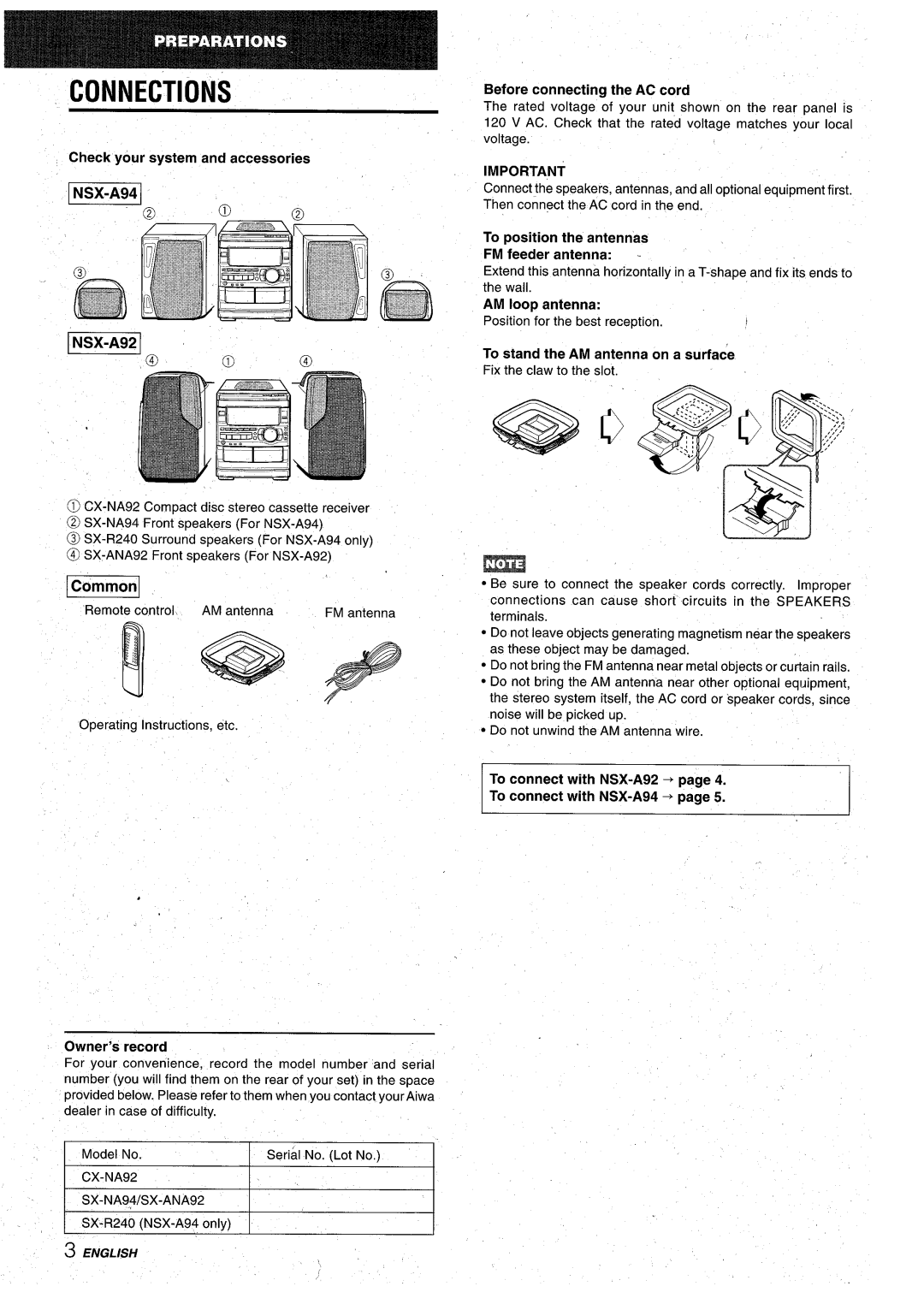
CX-NA92 specifications
The Aiwa CX-NA92 is a remarkable mini hi-fi system that emerged in the early 1990s, appealing to audiophiles and casual listeners alike with its impressive features and innovative technology. This compact yet powerful unit showcases Aiwa's commitment to delivering high-quality sound in a stylish package.At the heart of the CX-NA92 is its dual cassette deck, allowing users to play and record audio from cassette tapes. This feature, coupled with a simple interface for dubbing and playback, made it a popular choice during the time when cassette tapes were still widely used. The system also supports normal, chrome, and metal tapes, providing flexibility and excellent playback quality across various tape formats.
The system boasts a CD player that supports standard audio CDs, offering crystal-clear sound reproduction and a user-friendly interface for easy navigation through tracks. A notable feature is the CD synchro recording capability, allowing users to create mixed tapes directly from CDs. The inclusion of an AM/FM tuner further enhances its versatility, enabling users to enjoy a wide range of radio stations.
Sound quality is a significant highlight of the Aiwa CX-NA92. It is equipped with stereo speakers that deliver robust bass and crisp highs. The system's built-in equalizer allows users to tailor their listening experience, adjusting the sound according to personal preferences or specific genres. The powerful amplifier ensures that sound clarity is maintained even at higher volumes, making it suitable for both quiet evenings and lively gatherings.
Connectivity options include multiple audio inputs, allowing users to connect various external devices, such as turntables or additional sound sources. The design of the CX-NA92 prioritizes aesthetics as well, featuring a sleek, modern look that complements any home décor.
Another notable characteristic is its compact size, which makes it easy to fit into smaller spaces without compromising audio quality. Its user-friendly controls and remote compatibility enhance convenience, making it accessible for users of all ages.
Overall, the Aiwa CX-NA92 stands as a testament to the era of mini hi-fi systems, blending classic audio technologies with user-centric features. Its combination of a cassette deck, CD player, radio tuner, and impressive sound quality continues to endear it to collectors and retro audio enthusiasts today. Whether reminiscing about the past or simply enjoying the warm sound of analog, the CX-NA92 remains a cherished piece of audio equipment.

