ASSEMBLY
ASSEMBLY
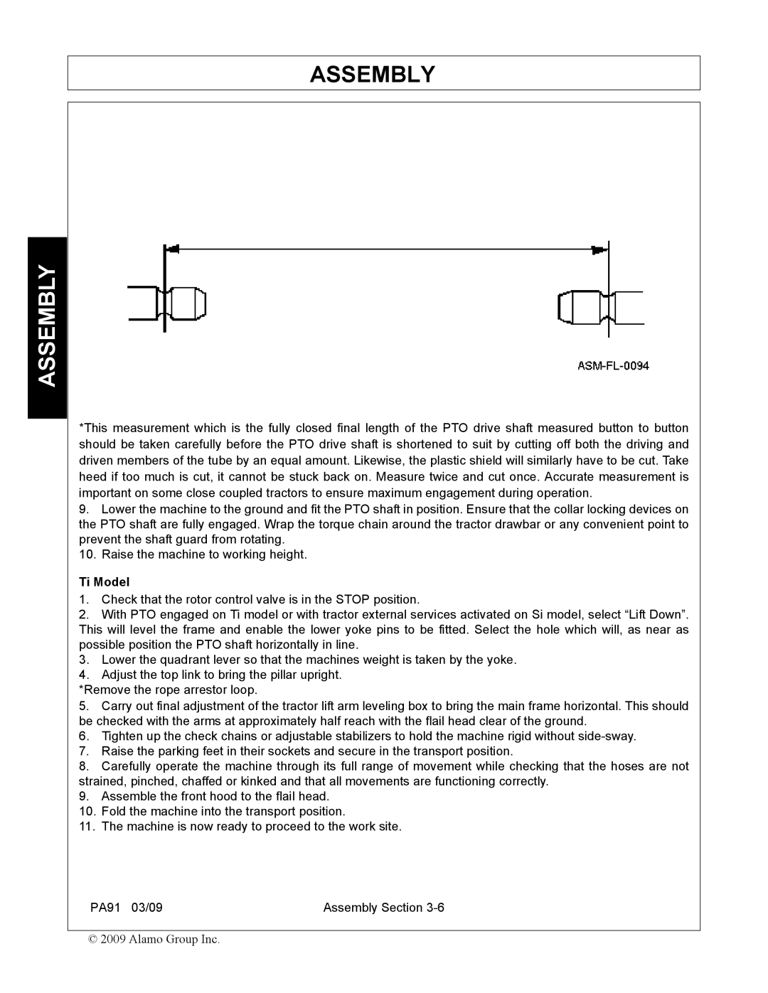
*This measurement which is the fully closed final length of the PTO drive shaft measured button to button should be taken carefully before the PTO drive shaft is shortened to suit by cutting off both the driving and driven members of the tube by an equal amount. Likewise, the plastic shield will similarly have to be cut. Take heed if too much is cut, it cannot be stuck back on. Measure twice and cut once. Accurate measurement is important on some close coupled tractors to ensure maximum engagement during operation.
9.Lower the machine to the ground and fit the PTO shaft in position. Ensure that the collar locking devices on the PTO shaft are fully engaged. Wrap the torque chain around the tractor drawbar or any convenient point to prevent the shaft guard from rotating.
10.Raise the machine to working height.
Ti Model
1.Check that the rotor control valve is in the STOP position.
2.With PTO engaged on Ti model or with tractor external services activated on Si model, select “Lift Down”. This will level the frame and enable the lower yoke pins to be fitted. Select the hole which will, as near as possible position the PTO shaft horizontally in line.
3.Lower the quadrant lever so that the machines weight is taken by the yoke.
4.Adjust the top link to bring the pillar upright.
*Remove the rope arrestor loop.
5.Carry out final adjustment of the tractor lift arm leveling box to bring the main frame horizontal. This should be checked with the arms at approximately half reach with the flail head clear of the ground.
6.Tighten up the check chains or adjustable stabilizers to hold the machine rigid without
7.Raise the parking feet in their sockets and secure in the transport position.
8.Carefully operate the machine through its full range of movement while checking that the hoses are not strained, pinched, chaffed or kinked and that all movements are functioning correctly.
9.Assemble the front hood to the flail head.
10.Fold the machine into the transport position.
11.The machine is now ready to proceed to the work site.
PA91 03/09 | Assembly Section |
© 2009 Alamo Group Inc.