OPERATION
OPERATION
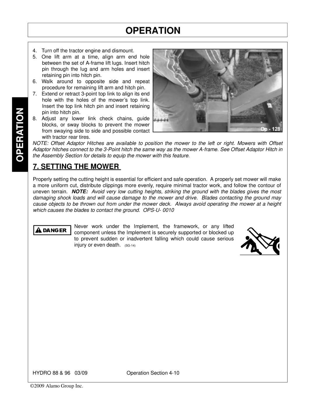
4.Turn off the tractor engine and dismount.
5.One lift arm at a time, align arm end hole between the set of
6.Walk around to opposite side and repeat procedure for remaining lift arm and hitch pin.
7.Extend or retract
8.Adjust any lower link check chains, guide blocks, or sway blocks to prevent the mower from swaying side to side and possible contact
with tractor rear tires.
NOTE: Offset Adaptor Hitches are available to position the mower to the left or right. Mowers with Offset Adaptor hitches connect to the
7. SETTING THE MOWER
Properly setting the cutting height is essential for efficient and safe operation. A properly set mower will make a more uniform cut, distribute clippings more evenly, require minimal tractor work, and follow the contour of uneven terrain. NOTE: Avoid very low cutting heights, striking the ground with the blades gives the most damaging shock loads and will cause damage to the mower and drive. Blades contacting the ground may cause objects to be thrown out from under the mower deck. Always avoid operating the mower at a height which causes the blades to contact the ground.
Never work under the Implement, the framework, or any lifted component unless the Implement is securely supported or blocked up to prevent sudden or inadvertent falling which could cause serious injury or even death.
HYDRO 88 & 96 03/09 | Operation Section |
©2009 Alamo Group Inc.