OPERATION
When fitting the mower to the tractor, the telescoping driveline must be inspected to ensure that at its most compressed position, the profiles do not “bottom out”, and when at its farthest extended position, there is sufficient engagement between the profiles to operate safely. At its shortest length, there must be at least a 1” clearance between each profile end and opposite profile universal joint. At its farthest operating extension, a minimum profile engagement of 12” must be maintained.
8. PUMP & SPEED INCREASER ATTACHMENT
OPERATION
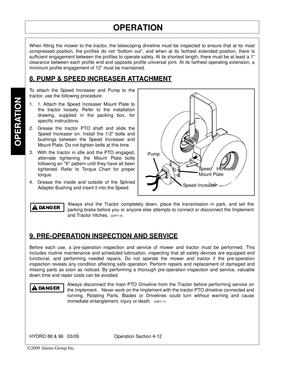
To attach the Speed Increaser and Pump to the tractor, use the following procedure:
1.1. Attach the Speed Increaser Mount Plate to the tractor loosely. Refer to the installation drawing, supplied in the packing box, for specific instructions.
2.Grease the tractor PTO shaft and slide the Speed Increaser on. Install the 1/2" bolts and bushings between the Speed Increaser and Mount Plate. Do not tighten bolts at this time.
3.With the tractor in idle and the PTO engaged, alternate tightening the Mount Plate bolts following an "X" pattern until they have all been tightened. Refer to Torque Chart for proper torque.
4.Grease the inside and outside of the Splined Adapter Bushing and insert it into the Speed
Pump
Speed Increaser
![]() Mount Plate
Mount Plate
![]() Speed Increaser
Speed Increaser
Always shut the Tractor completely down, place the transmission in park, and set the parking brake before you or anyone else attempts to connect or disconnect the Implement and Tractor hitches.
9. PRE-OPERATION INSPECTION AND SERVICE
Before each use, a
Always disconnect the main PTO Driveline from the Tractor before performing service on the Implement. Never work on the Implement with the tractor PTO driveline connected and running. Rotating Parts, Blades or Drivelines could turn without warning and cause immediate entanglement, injury or death.
HYDRO 88 & 96 03/09 | Operation Section |
©2009 Alamo Group Inc.