Commissioning
ACT 250 remote connector characteristics
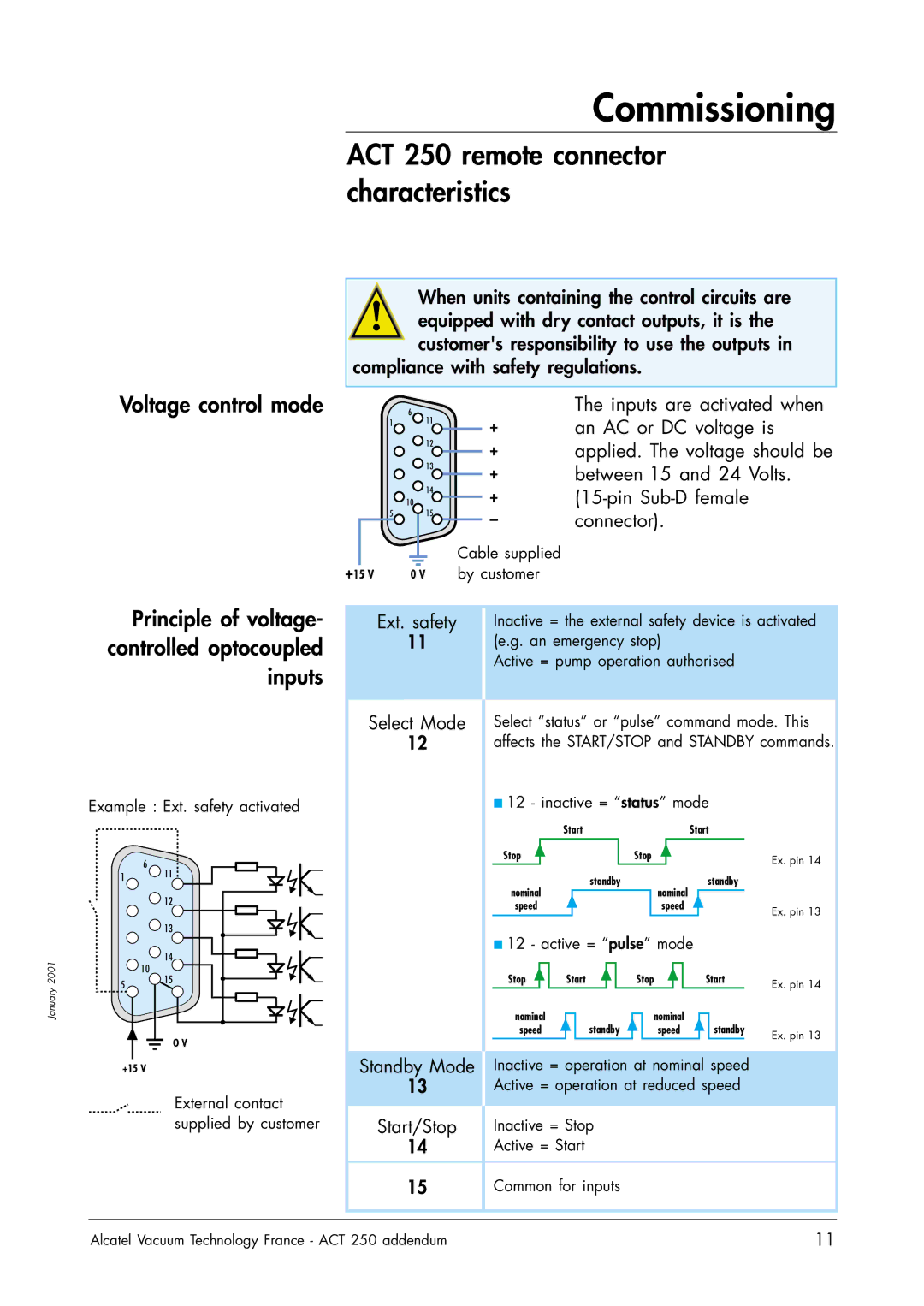
Voltage control mode
When units containing the control circuits are equipped with dry contact outputs, it is the customer's responsibility to use the outputs in
compliance with safety regulations.
| 6 |
|
| The inputs are activated when |
| 1 | 11 | + | an AC or DC voltage is |
|
| 12 | ||
|
| + | applied. The voltage should be | |
|
| 13 | ||
|
| + | between 15 and 24 Volts. | |
|
|
| ||
|
| 14 | + | |
| 10 | 15 | ||
| 5 | – | connector). | |
|
|
| ||
+15 V |
|
| Cable supplied |
|
0 V |
| by customer |
|
January 2001
Principle of voltage- controlled optocoupled inputs
Example : Ext. safety activated
| 6 |
1 | 11 |
| 12 |
| 13 |
| 14 |
| 10 |
5 | 15 |
|
O V
Ext. safety
11
Select Mode
12
Inactive = the external safety device is activated (e.g. an emergency stop)
Active = pump operation authorised
Select “status” or “pulse” command mode. This affects the START/STOP and STANDBY commands.
■12 - inactive = “status” mode
| Start |
|
|
|
| Start | ||||
Stop |
|
|
| Stop |
|
|
|
| Ex. pin 14 | |
nominal | standby |
|
| nominal |
| standby | ||||
|
|
|
|
|
|
| ||||
speed |
|
|
| speed |
|
| Ex. pin 13 | |||
■12 - active = “pulse” mode
Stop |
|
| Start |
|
| Stop |
|
| Start |
| Ex. pin 14 | |||
nominal |
|
| standby |
| nominal |
| standby |
| ||||||
|
|
|
|
| ||||||||||
speed |
|
|
| speed |
| Ex. pin 13 | ||||||||
|
|
|
|
|
|
|
|
|
|
|
|
|
| |
+15 V
External contact supplied by customer
Standby Mode Inactive = operation at nominal speed
13Active = operation at reduced speed
Start/Stop | Inactive = Stop |
14Active = Start
15Common for inputs
Alcatel Vacuum Technology France - ACT 250 addendum | 11 |
