Commissioning
ACT 250 remote connector wiring
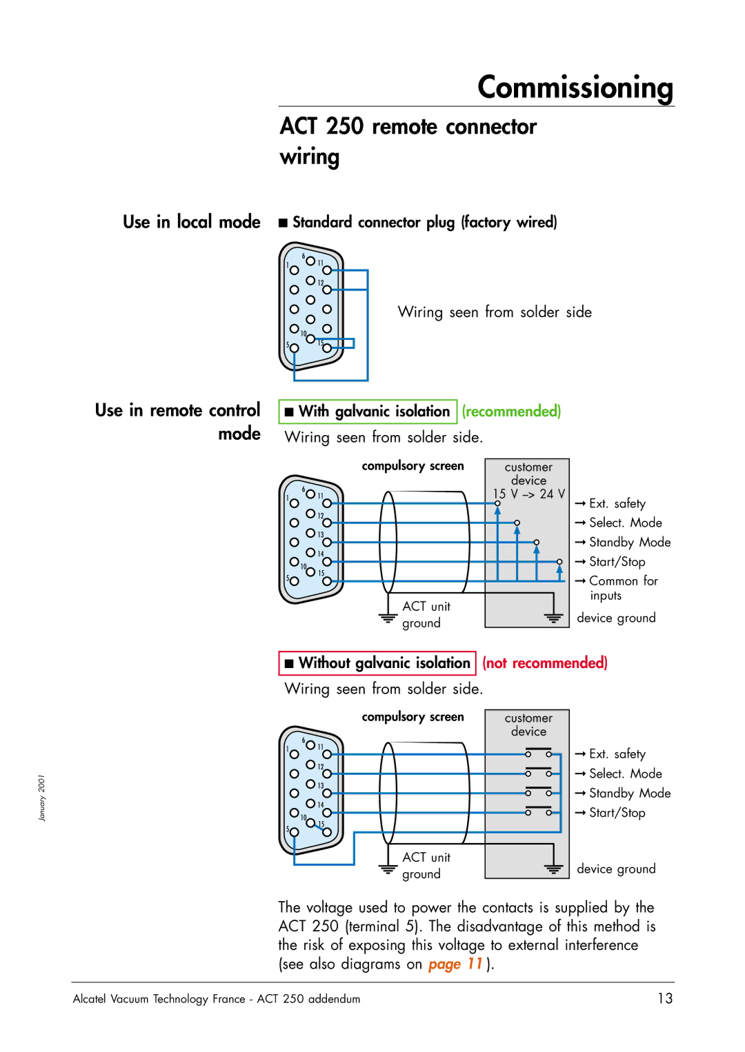
Use in local mode ■ Standard connector plug (factory wired)
6
111 ![]() 12
12
![]() 10
10
5![]() 15
15
Wiring seen from solder side
Use in remote control mode
■With galvanic isolation (recommended)
Wiring seen from solder side.
| compulsory screen | customer |
| 6 | device |
| 15 V | |
1 | 11 | |
| 12 |
|
| 13 |
|
| 14 |
|
| 10 |
|
5 | 15 |
|
|
| |
| ACT unit |
|
| ground |
|
➞Ext. safety
➞Select. Mode
➞Standby Mode
➞Start/Stop
➞Common for inputs
device ground
■ Without galvanic isolation (not recommended)
Wiring seen from solder side.
2001
6
111 ![]() 12
12 ![]() 13
13
compulsory screen | customer | ||
| device | ||
|
|
|
|
|
|
|
|
|
|
|
|
➞ Ext. safety |
➞ Select. Mode |
➞ Standby Mode |
January
![]() 10
10
14
➞ Start/Stop |
5![]()
15
ACT unit ground
device ground
The voltage used to power the contacts is supplied by the ACT 250 (terminal 5). The disadvantage of this method is the risk of exposing this voltage to external interference (see also diagrams on page 11 ).
Alcatel Vacuum Technology France - ACT 250 addendum | 13 |