4000 Series specifications
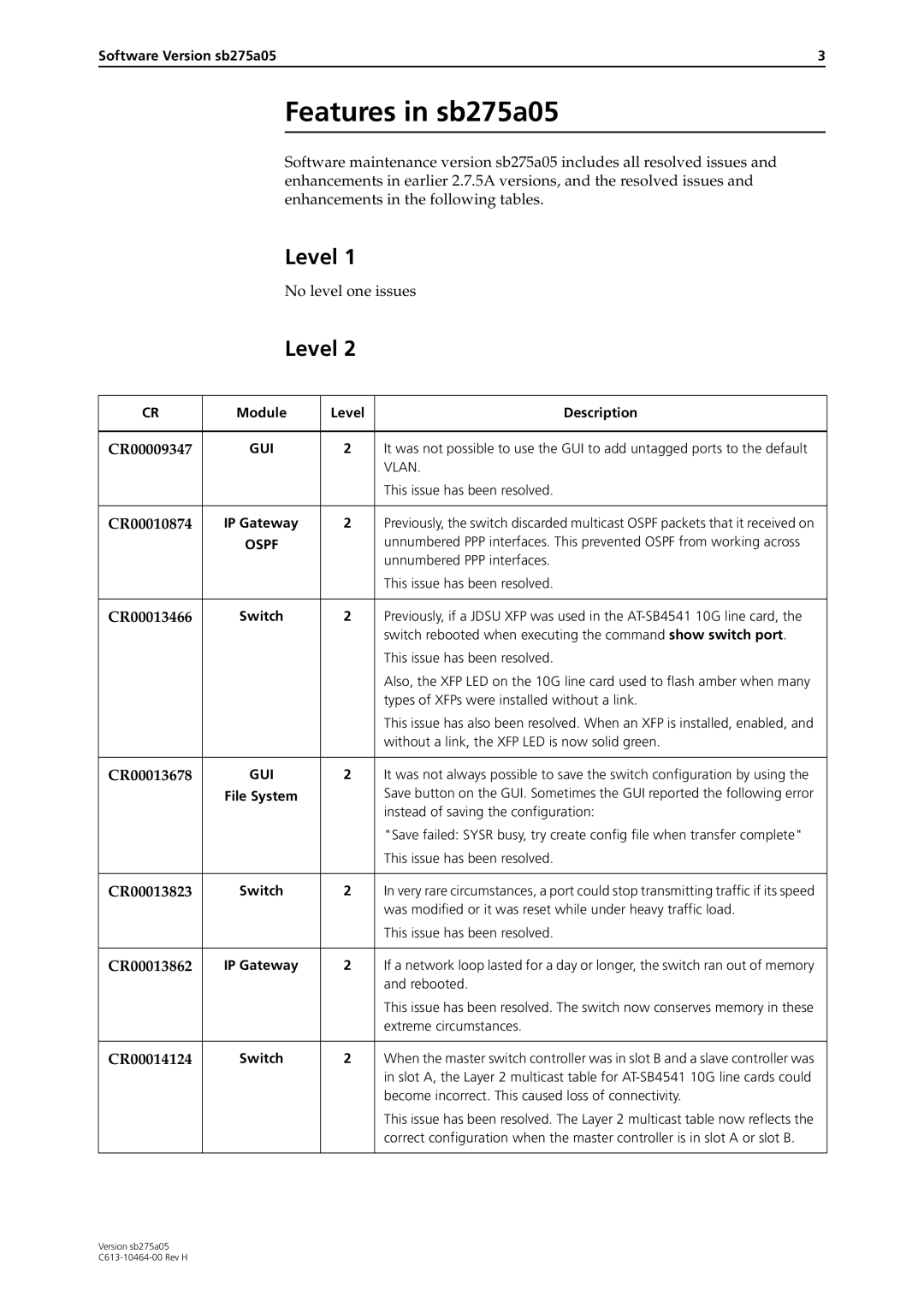
The Allied Telesis 4000 Series is designed to meet the growing demands for reliable and scalable networking solutions in enterprise environments. This series offers a range of stackable, Layer 2 and Layer 3 Ethernet switches, combining advanced features with robust performance to ensure seamless connectivity and superior network management.One of the standout features of the Allied Telesis 4000 Series is its versatile stacking capability. The switches can be stacked together, enabling them to function as a single unit. This simplifies network management and provides enhanced redundancy, allowing for easy scaling without disrupting operations. The stacking technology supports high-speed interconnections, ensuring that data transfer between switches remains efficient and reliable.
The 4000 Series is equipped with advanced Layer 2 and Layer 3 switching functionalities. This dual-layer capability allows for both basic data linking and more complex routing operations, providing a flexible solution for organizations with diverse networking needs. With support for VLAN segmentation, organizations can optimize their bandwidth usage and enhance security by isolating network traffic.
Security is a crucial aspect of the Allied Telesis 4000 Series. Features such as IEEE 802.1X port-based access control, dynamic VLAN assignment, and advanced access control lists (ACLs) ensure that unauthorized access is prevented. The switches also support secure management protocols, providing peace of mind for network administrators who need to maintain compliance with industry regulations.
The Allied Telesis 4000 Series integrates Power over Ethernet (PoE) technology, enabling the switches to supply power to connected devices, such as IP cameras and VoIP phones, directly through the Ethernet cable. This eliminates the need for separate power supplies, simplifying installation and reducing clutter, particularly in environments where space is at a premium.
For performance, the 4000 Series boasts high throughput and low latency, making it suitable for bandwidth-intensive applications. The switches come equipped with advanced Quality of Service (QoS) features, allowing network administrators to prioritize critical traffic and ensure that applications perform optimally, even during peak usage times.
In conclusion, the Allied Telesis 4000 Series offers a comprehensive solution for organizations seeking reliable, secure, and scalable networking equipment. With its advanced stacking capabilities, dual-layer functionality, robust security features, and PoE support, this series is well-suited for modern enterprise networking demands. Whether for a small office or a larger data center, the Allied Telesis 4000 Series delivers the performance and flexibility required in today’s dynamic networking environments.
