Front and Back Panels
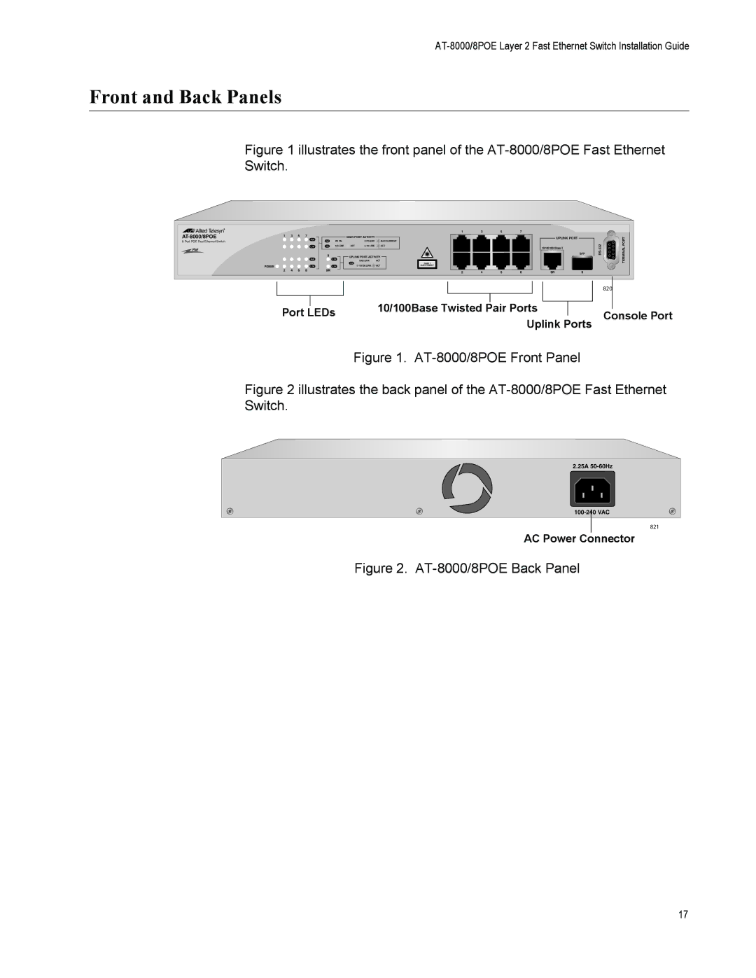
Figure 1 illustrates the front panel of the AT-8000/8POE Fast Ethernet
Switch.
AT-8000/8POE
1 3 5 7
MAINDETPORTON ON ACTIVITY
1 | 3 | 5 | 7 |
UPLINK PORT
8 Port POE Fast Ethernet Switch
PoE
POWER ![]()
2 4 6 8
PD ON |
| PD ERR | MAX CURRENT |
100 LINK | ACT | 10 LINK | ACT |
9UPLINK PORT ACTIVITY
1000 LINK | ACT | CLASS 1 |
|
| |
10/100 LINK | ACT | LASER PRODUCT |
9R
10/100/1000
SFP
2 | 4 | 6 | 8 | 9R | 9 |
|
|
|
|
|
|
|
|
|
| 820 |
|
|
|
|
|
|
|
|
|
|
|
|
|
| |
|
|
| 10/100Base Twisted |
| Pair Ports |
|
|
|
|
| ||
| Port LEDs |
|
|
| Console Port | |||||||
|
|
|
| Uplink Ports | ||||||||
|
|
|
|
|
| |||||||
Figure 1. AT-8000/8POE Front Panel
Figure 2 illustrates the back panel of the AT-8000/8POE Fast Ethernet Switch.
2.25A |
821 |
AC Power Connector
Figure 2. AT-8000/8POE Back Panel
17