Chapter 1: Overview
LEDs
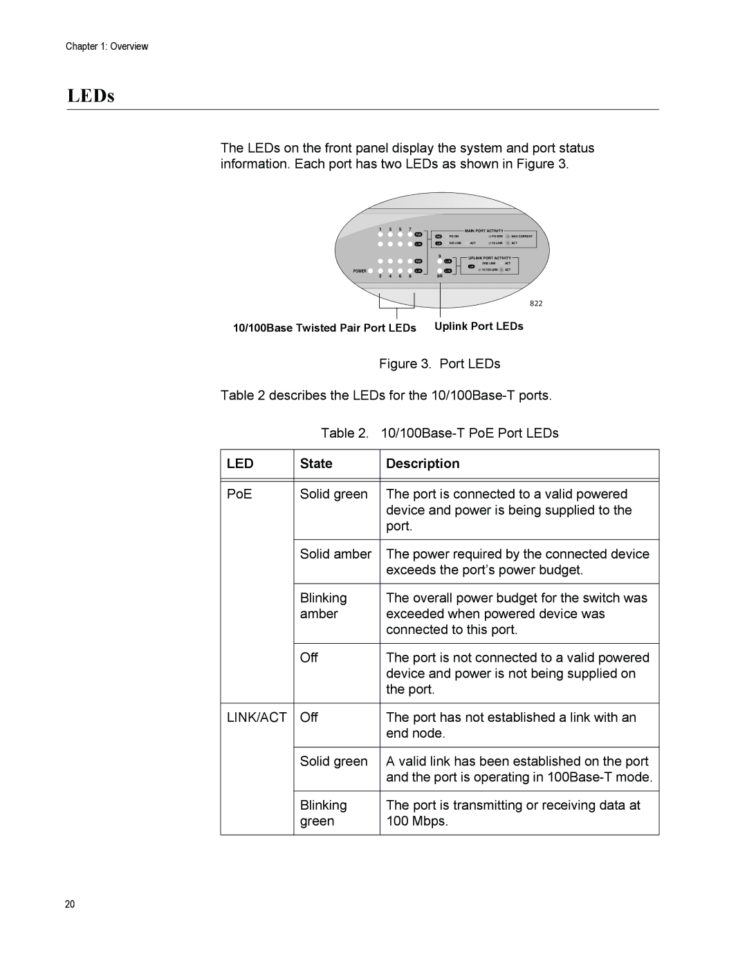
The LEDs on the front panel display the system and port status information. Each port has two LEDs as shown in Figure 3.
1 3 5 7
POWER 


 2 4 6 8
MAIN PORT ACTIVITY
PD ON |
| PD ERR | MAX CURRENT |
100 LINK | ACT | 10 LINK | ACT |
9UPLINK PORT ACTIVITY
![]() 1000 LINK
1000 LINK ![]() ACT
ACT
![]() 10/100 LINK
10/100 LINK ![]() ACT
ACT
9R
822
10/100Base Twisted Pair Port LEDs Uplink Port LEDs
Figure 3. Port LEDs
Table 2 describes the LEDs for the 10/100Base-T ports.
Table 2. 10/100Base-T PoE Port LEDs
LED | State | Description |
|
|
|
|
|
|
PoE | Solid green | The port is connected to a valid powered |
|
| device and power is being supplied to the |
|
| port. |
|
|
|
| Solid amber | The power required by the connected device |
|
| exceeds the port’s power budget. |
|
|
|
| Blinking | The overall power budget for the switch was |
| amber | exceeded when powered device was |
|
| connected to this port. |
|
|
|
| Off | The port is not connected to a valid powered |
|
| device and power is not being supplied on |
|
| the port. |
|
|
|
LINK/ACT | Off | The port has not established a link with an |
|
| end node. |
|
|
|
| Solid green | A valid link has been established on the port |
|
| and the port is operating in |
|
|
|
| Blinking | The port is transmitting or receiving data at |
| green | 100 Mbps. |
|
|
|
20
