Contents
Introduction
Query solicitation rapid recovery from topology changes
How clients leave groups queries and timers
Configurable Igmp timers and counters
Example of bad choices for timer values
Products and software versions this note applies to
Igmp feature Software versions Products
4 AlliedWare OS How To Note Igmp
5 AlliedWare OS How To Note Igmp
Igmp overview
Queriers and Snoopers
6 AlliedWare OS How To Note Igmp
Messages
7 AlliedWare OS How To Note Igmp
Choosing group addresses
IP address, binary
MAC address, hex
8 AlliedWare OS How To Note Igmp
Avoid x.0.0.y, x.0.1.y, x.128.0.y, and x.128.1.y
9 AlliedWare OS How To Note Igmp
Igmp snooping
Example
Configure switch
10 AlliedWare OS How To Note Igmp
11 AlliedWare OS How To Note Igmp
Explanation of Igmp snooping
Using Show command output to investigate Igmp state
Group List Entry timeout 136 secs Ports None
Group List Entry timeout 257 Secs Ports All Groups 235
12 AlliedWare OS How To Note Igmp
13 AlliedWare OS How To Note Igmp
Group Last Adv
When a client leaves a group
Group List Entry timeout 247 secs Ports
14 AlliedWare OS How To Note Igmp
15 AlliedWare OS How To Note Igmp
Multiple potential Igmp queriers
16 AlliedWare OS How To Note Igmp
When there are no group members
Other Querier timeout .. secs
17 AlliedWare OS How To Note Igmp
When a client joins a group
Group List Entry timeout 225 secs Ports
All Groups Entry timeout Secs Ports
18 AlliedWare OS How To Note Igmp
19 AlliedWare OS How To Note Igmp
Group List
Group List Last Adv
20 AlliedWare OS How To Note Igmp
21 AlliedWare OS How To Note Igmp
Igmp proxy
Switch 3 is an Igmp Proxy
22 AlliedWare OS How To Note Igmp
Group List Entry timeout 122 secs Ports None
All Groups Entry timeout 145 Secs Ports
23 AlliedWare OS How To Note Igmp
Explanation of Igmp proxy
Group Entry timeout Secs Ports
24 AlliedWare OS How To Note Igmp
Group Entry timeout 182 secs Ports
25 AlliedWare OS How To Note Igmp
Query solicitation rapid recovery from topology changes
26 AlliedWare OS How To Note Igmp
How query solicitation works
27 AlliedWare OS How To Note Igmp
Initial state
Why convergence takes so long without query solicitation
28 AlliedWare OS How To Note Igmp
Example
Explanation from the perspective of switch 2, the snooper
29 AlliedWare OS How To Note Igmp
All Groups Entry timeout 236 secs Ports
30 AlliedWare OS How To Note Igmp
Explanation from the perspective of switch 1, the querier
Group Entry timeout 18 secs Ports
31 AlliedWare OS How To Note Igmp
Shows this entry
Group Entry timeout 115 secs Ports
32 AlliedWare OS How To Note Igmp
33 AlliedWare OS How To Note Igmp
Speeding up Igmp convergence in a non-looped topology
34 AlliedWare OS How To Note Igmp
Switch 1 sends GQ
35 AlliedWare OS How To Note Igmp
Igmp filtering controlling multicast distribution
Types command
Set switch port=1 igmpfilter=1
36 AlliedWare OS How To Note Igmp
Switch 3 is also an Igmp Snooper
37 AlliedWare OS How To Note Igmp
38 AlliedWare OS How To Note Igmp
Received Passed Dropped
39 AlliedWare OS How To Note Igmp
No group memberships
40 AlliedWare OS How To Note Igmp
41 AlliedWare OS How To Note Igmp
42 AlliedWare OS How To Note Igmp
43 AlliedWare OS How To Note Igmp
44 AlliedWare OS How To Note Igmp
45 AlliedWare OS How To Note Igmp
When we deny groups instead of replacing them
Modify switch 2 Configuration
46 AlliedWare OS How To Note Igmp
Group 224.12.13.11 Entry timeout 255 secs Ports 224.12.13.12
47 AlliedWare OS How To Note Igmp
48 AlliedWare OS How To Note Igmp
Static Igmp
Switch 2 is an Igmp Snooper
49 AlliedWare OS How To Note Igmp
50 AlliedWare OS How To Note Igmp
Group Entry timeout Infinity Ports
51 AlliedWare OS How To Note Igmp
Explanation of Static Igmp
When we add a static entry on another switch
Modify switch 3 Configuration
52 AlliedWare OS How To Note Igmp
MulticastPkts 675826
All Groups Entry timeout 247 secs Ports
53 AlliedWare OS How To Note Igmp
54 AlliedWare OS How To Note Igmp
Group Entry timeout Infinity Ports 5,26
55 AlliedWare OS How To Note Igmp
56 AlliedWare OS How To Note Igmp
MulticastPkts 36350
MulticastPkts 14756
When a static entry’s port goes down
Group Entry timeout Infinity Ports None
57 AlliedWare OS How To Note Igmp
How clients leave groups queries and timers
Querier timer values
58 AlliedWare OS How To Note Igmp
Overview of leave process
Snooper timer values
59 AlliedWare OS How To Note Igmp
Comparing the Querier and Snooper timers
60 AlliedWare OS How To Note Igmp
Consequences for high-loss and high-lag networks
Describes the new behaviour
61 AlliedWare OS How To Note Igmp
Igmp fast leave
Switch 1 is an Igmp Querier
62 AlliedWare OS How To Note Igmp
63 AlliedWare OS How To Note Igmp
Explanation of Igmp fast leave
When fast leave is disabled
Group Entry timeout 2 secs Ports
64 AlliedWare OS How To Note Igmp
Fast Leave Off
When you enable fast leave on switch
It is safe to ignore the group entry on switch
Group Entry timeout Secs Ports None
65 AlliedWare OS How To Note Igmp
When you set fast leave on all interfaces
66 AlliedWare OS How To Note Igmp
Multiple host mode for fast leave
To specify multiple mode, use the command
To specify single mode, use either of the commands
67 AlliedWare OS How To Note Igmp
68 AlliedWare OS How To Note Igmp
Configurable Igmp timers and counters
Timer and counter relationships
69 AlliedWare OS How To Note Igmp
Initial configuration
Each example modifies the following base configuration
70 AlliedWare OS How To Note Igmp
Software versions
71 AlliedWare OS How To Note Igmp
Default values
72 AlliedWare OS How To Note Igmp
Last Member Query Count and Last Member Query Interval
What these counters do
Potential problems with changing these counters
How to change these counters
73 AlliedWare OS How To Note Igmp
Last Member Query Interval 255 10secs
74 AlliedWare OS How To Note Igmp
Last Member Query Count
Potential problems with changing this counter
How to change this counter
Robustness Variable
What this counter does
Default Query Interval
What this timer does
Potential problems with changing this timer
How to change this timer
77 AlliedWare OS How To Note Igmp
Query Response Interval
Query Response Interval 100 10secs
Default Timeout Interval
Synchronisation of timers
78 AlliedWare OS How To Note Igmp
Default Timeout Interval = 2*130 + 100/10 = 270 seconds
79 AlliedWare OS How To Note Igmp
Default Timeout Interval = 2*125 + 100/10 = 260 seconds
Default Timeout Interval 280 Secs
80 AlliedWare OS How To Note Igmp
Query Response Interval 200 10secs
Default Timeout Interval 180 Secs
81 AlliedWare OS How To Note Igmp
Default Query Interval 200 Secs Default Timeout Interval 410
82 AlliedWare OS How To Note Igmp
Example of bad choices for timer values
Imagine the following changes to the configuration
Commands to configure these settings are
83 AlliedWare OS How To Note Igmp
Problem 1 Last Member Query Interval too short
Problem 2 Query Response Interval short
Problem 3 Default Timeout Interval too short
Last Member Query Interval was set to 5, using the command
For more information, see Synchronisation of timers on
85 AlliedWare OS How To Note Igmp
86 AlliedWare OS How To Note Igmp
Stopping snoopers from snooping non-IGMP messages
87 AlliedWare OS How To Note Igmp
Configure the router
88 AlliedWare OS How To Note Igmp
Router uses Ospf
Ports 24
89 AlliedWare OS How To Note Igmp
Ports 25
Disabled All-groups Ports
90 AlliedWare OS How To Note Igmp
Preventing an All Groups entry for a port
Disabling All Groups entry for a port
Check the group entry timeout values
Reset port 24’s packet counters
Entry timeout 216 Secs
Enabling All Groups entry again
Check the group entry timeout values again
Entry timeout Secs
92 AlliedWare OS How To Note Igmp
MulticastPkts
Enable Igmp debugging
Entry timeout 259 Secs
93 AlliedWare OS How To Note Igmp
94 AlliedWare OS How To Note Igmp
MulticastPkts 914
95 AlliedWare OS How To Note Igmp
Controlling which addresses create All Groups entries
Configuring switch
96 AlliedWare OS How To Note Igmp
224.0.0.5
97 AlliedWare OS How To Note Igmp
Configuring switches 1
98 AlliedWare OS How To Note Igmp
Adding other router addresses
Returning to the default list
99 AlliedWare OS How To Note Igmp
224.0.0.254
Using the other routermode options
100 AlliedWare OS How To Note Igmp
101 AlliedWare OS How To Note Igmp
Statically specifying that a port is a router port
Check the current Igmp snooping entries
To remove the static configuration, simply delete it
102 AlliedWare OS How To Note Igmp
Statically add port 6 as a router port attached to Vlan
Stop port 6 from being a static router port
103 AlliedWare OS How To Note Igmp
Igmp debugging
Client joins a group
IgmpSnoopMembershipQuery setting timer at 2 secs for group
104 AlliedWare OS How To Note Igmp
Client leaves a group
Several minutes later the group entry times out
Manager Switch 3 del vlan=100 port=5
105 AlliedWare OS How To Note Igmp
Port entry times out
Snooped ports change
106 AlliedWare OS How To Note Igmp
Report is filtered out
Port in the All Groups list is unplugged
107 AlliedWare OS How To Note Igmp
Output for show ip igmp changes
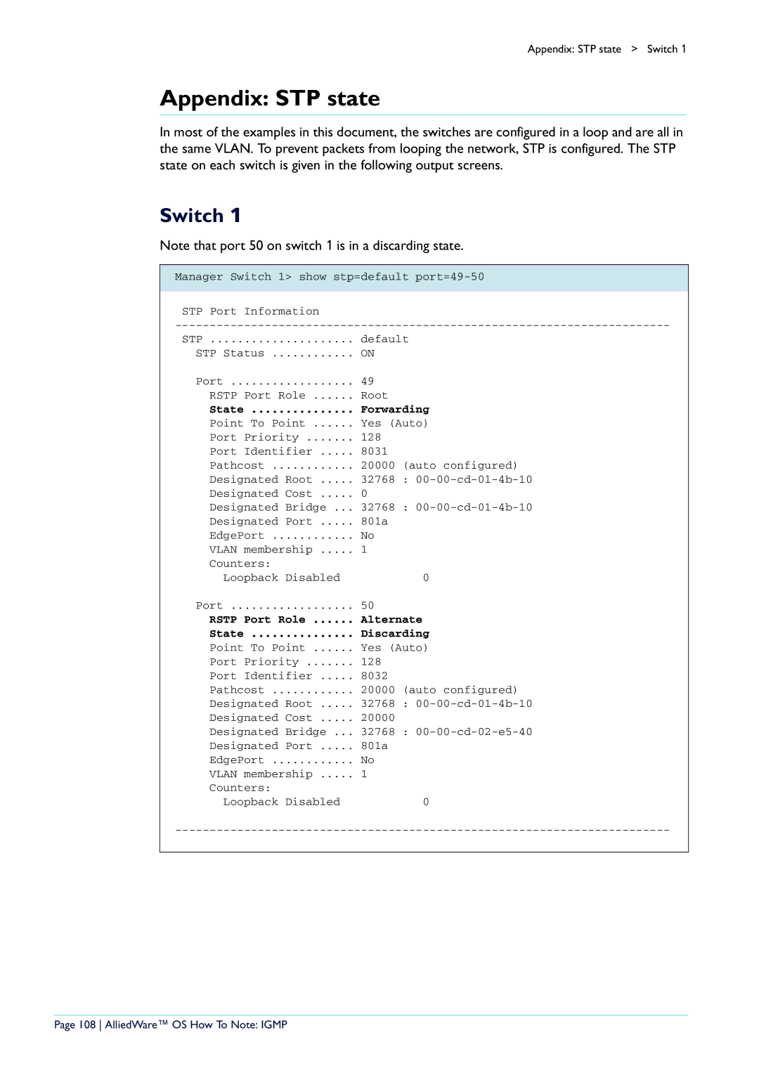
Switch
108 AlliedWare OS How To Note Igmp
Appendix STP state
State Forwarding
109 AlliedWare OS How To Note Igmp
Manager Switch 3 show stp port=25-26