Chapter 1: Product Description
AC Power
Connector
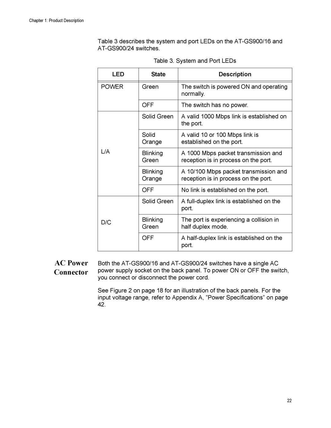
Table 3 describes the system and port LEDs on the
Table 3. System and Port LEDs
LED | State | Description | |
|
|
| |
|
|
| |
POWER | Green | The switch is powered ON and operating | |
|
| normally. | |
|
|
| |
| OFF | The switch has no power. | |
|
|
| |
| Solid Green | A valid 1000 Mbps link is established on | |
|
| the port. | |
|
|
| |
| Solid | A valid 10 or 100 Mbps link is | |
| Orange | established on the port. | |
L/A |
|
| |
Blinking | A 1000 Mbps packet transmission and | ||
| Green | reception is in process on the port. | |
|
|
| |
| Blinking | A 10/100 Mbps packet transmission and | |
| Orange | reception is in process on the port. | |
|
|
| |
| OFF | No link is established on the port. | |
|
|
| |
| Solid Green | A | |
|
| port. | |
|
|
| |
D/C | Blinking | The port is experiencing a collision in | |
Green | half duplex mode. | ||
| |||
|
|
| |
| OFF | A | |
|
| port. | |
|
|
|
Both the
See Figure 2 on page 18 for an illustration of the back panels. For the input voltage range, refer to Appendix A, ”Power Specifications” on page 42.
22
