Chapter 2: Installation
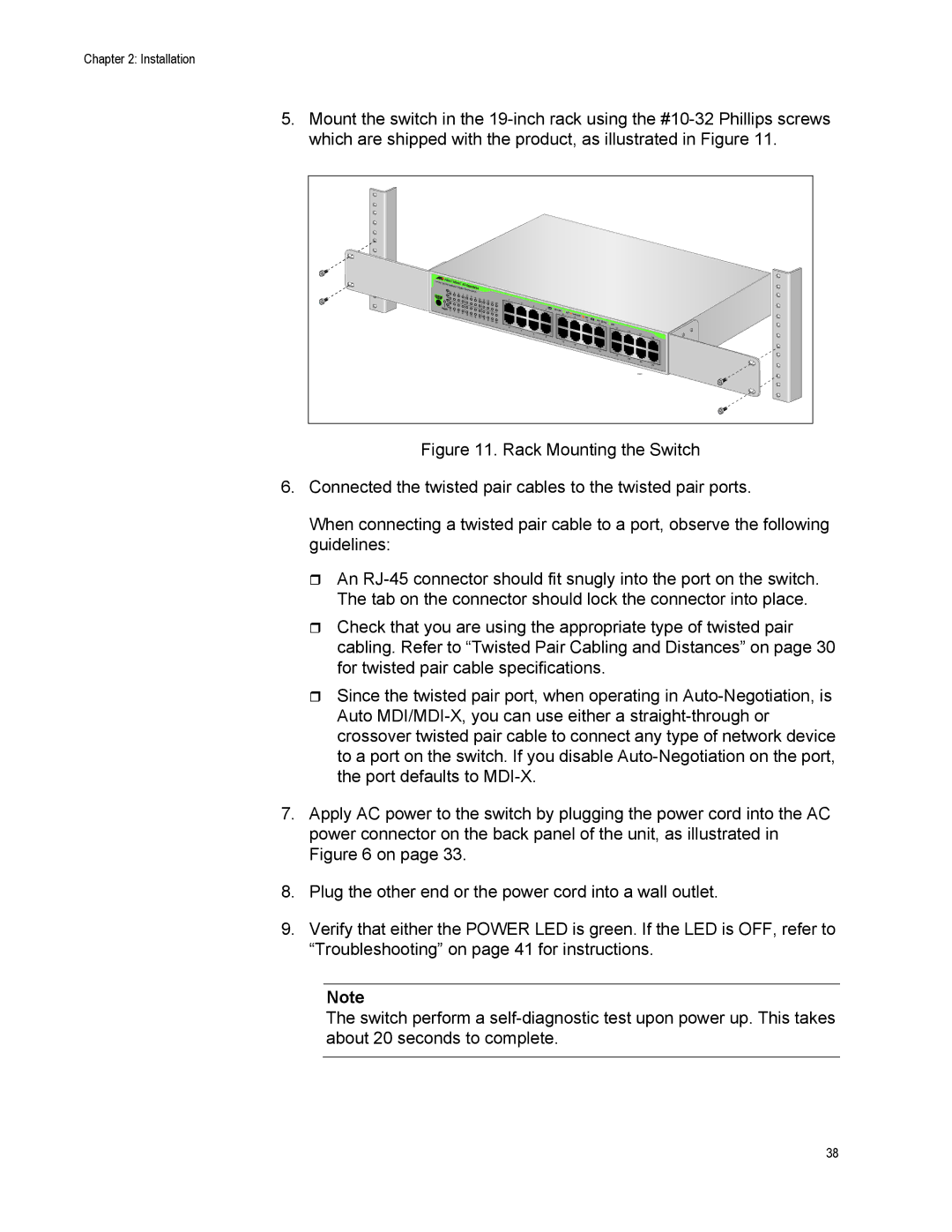
5.Mount the switch in the
24 Port |
|
|
|
|
|
|
|
|
|
|
|
|
|
|
|
|
|
|
|
|
| AT- | GS900/24 |
|
|
|
|
|
|
|
|
|
|
|
| ||||||
|
|
| Gigabit |
|
|
|
|
|
|
|
|
|
|
|
|
| ||||
| 1 | 3 |
|
| Ethernet | Switch |
|
|
|
|
|
|
|
|
|
|
|
| ||
| 5 | 7 |
|
|
|
|
|
|
|
|
|
|
|
|
|
|
| |||
|
|
|
|
|
| 9 | 11 | 13 | 15 |
|
|
|
|
|
|
|
|
|
|
|
|
|
|
|
|
|
|
| 17 | 19 |
|
| 1 |
|
|
|
|
|
| ||
|
|
|
|
|
|
|
|
|
| 21 | 23 |
|
|
|
|
|
| |||
|
|
|
|
|
|
|
|
|
|
|
| 3 |
|
|
|
|
|
| ||
POWER |
|
|
|
|
|
|
|
|
|
|
|
|
| 5 |
|
|
|
|
|
|
2 | 4 | 6 |
|
|
|
|
|
|
|
|
|
| 7 | 1000 LINK | ACT |
|
|
|
| |
|
| 8 | 10 |
|
|
|
|
|
|
|
| 9 | 10/100 |
|
|
| ||||
|
|
|
| 12 | 14 |
|
|
|
|
|
|
| LINK |
|
| |||||
|
|
|
|
|
|
|
|
|
|
|
|
|
|
| 11 |
|
| |||
|
|
|
|
|
|
|
|
| 16 | 18 | 20 |
|
|
|
|
|
| ACT | FDX |
|
|
|
|
|
|
|
|
|
|
|
| 22 | 24 |
|
|
|
| 13 | HDX | ||
|
|
|
|
|
|
|
|
|
|
|
|
|
|
|
|
|
|
| 15 | COL |
|
|
|
|
|
|
|
|
|
|
|
|
|
| 2 |
|
|
|
|
| 17 |
|
|
|
|
|
|
|
|
|
|
|
|
|
| 4 |
|
|
|
|
| 19 |
|
|
|
|
|
|
|
|
|
|
|
|
|
| 6 |
|
|
|
|
| 21 |
|
|
|
|
|
|
|
|
|
|
|
|
|
| 8 |
|
|
|
|
| 23 |
|
|
|
|
|
|
|
|
|
|
|
|
|
|
| 10 |
|
|
|
|
|
|
|
|
|
|
|
|
|
|
|
|
|
|
|
|
|
| 12 |
|
|
|
|
|
|
|
|
|
|
|
|
|
|
|
|
|
|
|
|
| 14 |
|
|
|
|
|
|
|
|
|
|
|
|
|
|
|
|
|
|
|
|
| 16 |
|
|
|
|
|
|
|
|
|
|
|
|
|
|
|
|
|
|
|
|
| 18 |
|
|
|
|
|
|
|
|
|
|
|
|
|
|
|
|
|
|
|
| 20 |
|
|
|
|
|
|
|
|
|
|
|
|
|
|
|
|
|
|
|
| 22 |
|
|
|
|
|
|
|
|
|
|
|
|
|
|
|
|
|
|
|
| 24 |
|
|
|
|
|
|
|
|
|
|
|
|
|
|
|
|
|
|
|
| 1921 |
Figure 11. Rack Mounting the Switch
6.Connected the twisted pair cables to the twisted pair ports.
When connecting a twisted pair cable to a port, observe the following guidelines:
An RJ-45 connector should fit snugly into the port on the switch. The tab on the connector should lock the connector into place.
Check that you are using the appropriate type of twisted pair cabling. Refer to “Twisted Pair Cabling and Distances” on page 30 for twisted pair cable specifications.
Since the twisted pair port, when operating in Auto-Negotiation, is Auto MDI/MDI-X, you can use either a straight-through or crossover twisted pair cable to connect any type of network device to a port on the switch. If you disable Auto-Negotiation on the port, the port defaults to MDI-X.
7.Apply AC power to the switch by plugging the power cord into the AC power connector on the back panel of the unit, as illustrated in Figure 6 on page 33.
8.Plug the other end or the power cord into a wall outlet.
9.Verify that either the POWER LED is green. If the LED is OFF, refer to “Troubleshooting” on page 41 for instructions.
Note
The switch perform a self-diagnostic test upon power up. This takes about 20 seconds to complete.
38