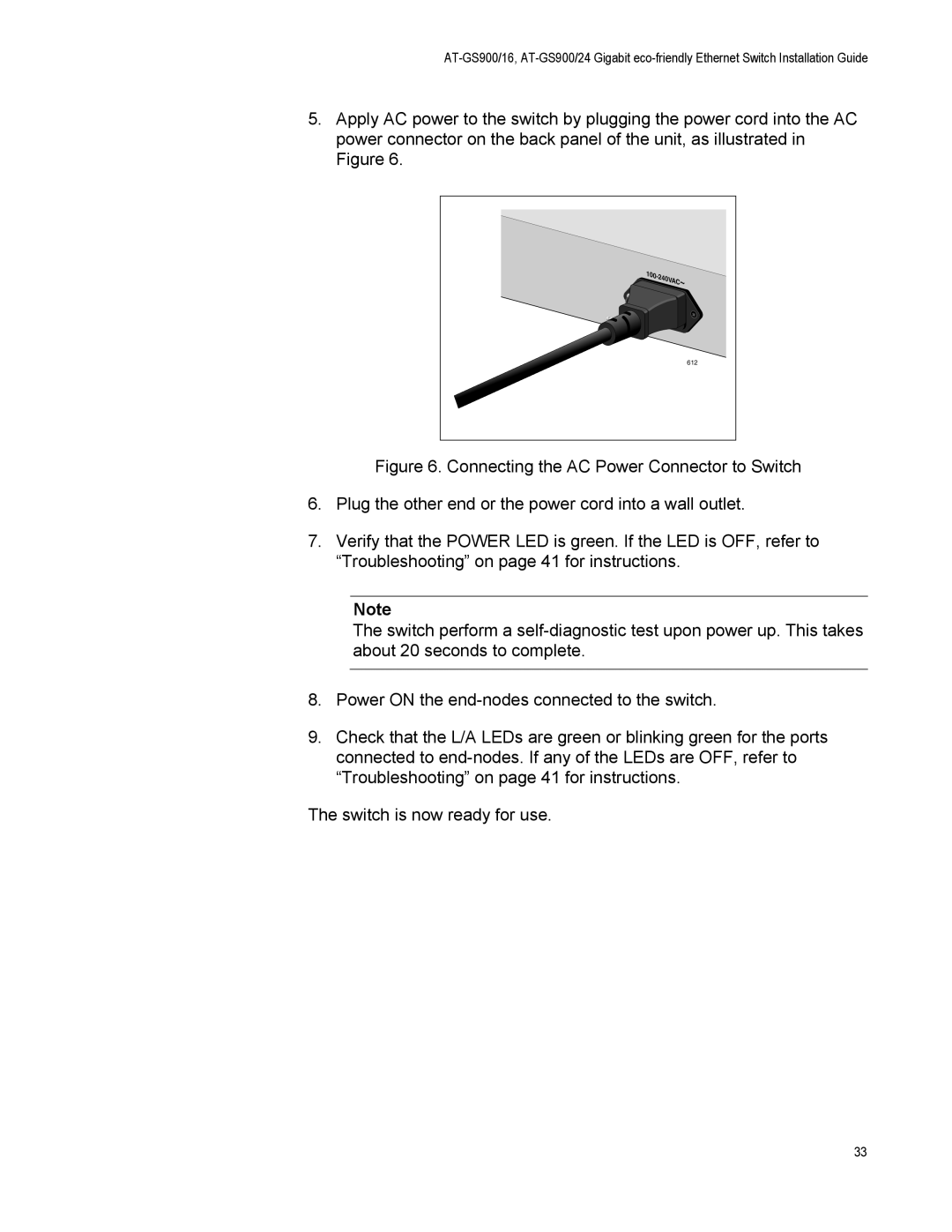
5.Apply AC power to the switch by plugging the power cord into the AC power connector on the back panel of the unit, as illustrated in Figure 6.
100 |
C~ |
612 |
Figure 6. Connecting the AC Power Connector to Switch
6.Plug the other end or the power cord into a wall outlet.
7.Verify that the POWER LED is green. If the LED is OFF, refer to “Troubleshooting” on page 41 for instructions.
Note
The switch perform a self-diagnostic test upon power up. This takes about 20 seconds to complete.
8.Power ON the end-nodes connected to the switch.
9.Check that the L/A LEDs are green or blinking green for the ports connected to end-nodes. If any of the LEDs are OFF, refer to “Troubleshooting” on page 41 for instructions.
The switch is now ready for use.
33