GSM-8T16SFP
Version March 1
Table of Contents
102
Federal Communications Commission FCC Statement
Electronic Emission Notices
Australian C-Tick Compliance
Terms Used
GSM Series
Overview of GSM Series Snmp Managed Switches
Introduction
Checklist
Key Features of GSM Series Snmp Managed Switches
Management
Features
Hardware
Overview of GSM Series Switches
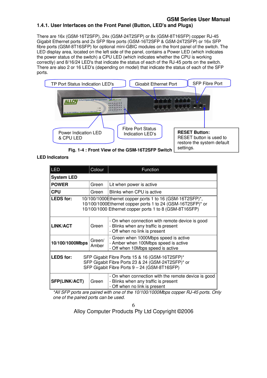
Front View of the GSM-16T2SFP Switch
Leds for
User Interfaces on the Front Panel Button, LEDs and Plugs
System LED
10/100/1000Mbps
Overview of the Optional SFP Modules
User Interfaces on the Rear Panel
Front View 1000Base-SX/LX LC SFP Fibre Transceiver
Installing Optional SFP Mini-GBIC Modules
Starting the GSM Series Snmp Managed Switches
Hardware and Cable Installation
Connecting the SFP Mini-GBIC Module to the Chassis
Power On
Copper Ports Cable Installation
Firmware Loading
Cabling Requirements
Multimode Fibre Cable and Modal Bandwidth
Username admin Password admin
Management options available with the GSM Series Switches
Baud Rate Data Bits Parity None Stop Bits Flow Control None
Page
Subnet Mask
Username admin Password admin
Operation of the Web Based Management
IP Address Subnet Mask
Web Management Home Overview
System Information Page Layout
System Information
Current Time
Bios Version
System Up Time
Firmware Version
Default Disabled IP Address
IP Configuration
Dhcp Setting
Default
Default Default Gateway
DNS
Time Configuration
Manual
Default +8 hours Daylight Savings
Default Default values for starting and ending date
Edit
Account Configuration
Create New
Delete
Confirm Password
Password
Username
Name
Management Security Configuration
IP Range
Action
Access Type
Incoming Port
Edit/Create
Role
Virtual Stack Configuration
State
Group ID
Port Configuration
Port Status
Default Enabled
Default Enabled Auto Negotiation
Default Enabled Speed / Duplex Mode
Port No
TX Central Wavelength
Connector Type
Fibre Type
Baud Rate
Vendor PN
Temperature
Vendor Name
Vendor Rev
Port Configuration
Default Auto Flow Control
Mode
RX Byte
Simple Counter
TX Byte
TX Packet
TX Collision
RX Error Packet
Reset
Refresh Interval
RX Octets
Detail Counter
RX Packets
RX High Priority Packets
TX Packets
RX Broadcast
RX Multicast
TX Octets
TX 512 ~ 1023 Bytes
RX Errors
TX 256 ~ 511 Bytes
TX 1024 Bytes
Default Port Monitored Port
Default Disable Monitoring Port
Mirror
Port Number
Default State Disable
Bandwidth
All Traffic for Ingress Rate Limiting Policing
Broadcast & Multicast for Ingress Rate Limiting Policing
Port
QOS Quality of Service
Class
Bit 0, Bit 1, Bit
Port
Prioritise IP Telephony VoIP
Disable IP TCP/UDP Port Classification
Down Prioritise web browsing, email, FTP and news
Prioritise iSCSI
Prioritise web browsing, email, FTP and news
Advanced Mode
Default Class All other TCP/UDP Ports
Prioritise Streaming Audio/Video
22 Advanced Mode
Diffserv
Snmp Configuration
Default Enable
Get/Set/Trap Community
Default for all public traps Enable
Trap
Igmp Snooping
Snooping Mode
Default Disable
Status
Passive
Disable
Active
IP Multicast Table
Allowed Group
Max. Packet Length
Max. Frame Size
Default Disable Delay Time
Dhcp Boot
Dhcp Broadcast Suppression
Vlan Virtual Local Area Network
Vlan Mode
Port-based
Tag-based
Metro Mode
Double-tag
GSM-16T2SFP 24 GSM-24T2SFP, GSM-8T16SFP
Uplink Port
GSM-16T2SFP 23 GSM-24T2SFP, GSM-8T16SFP
15 & 16 GSM-16T2SFP 23 & 24 GSM-24T2SFP, GSM-8T16SFP
Member
Tag-based Group
Vlan Name
Add
Settings to take effect
Port-based Group
Vlan Name
Edit
Tag Rule
Rule
Untag VID
Search
MAC Table
MAC Table Information
Alias
Next
Previous
MAC Address
Aging Time
MAC Table Maintenance
Flush
Static Forward
Static Filter
MAC Alias
Gvrp State Setting
Gvrp Configuration
Gvrp
Default Registrar Mode
Default Leave All Time
Default Applicant Mode
Restricted Mode
Gvrp Counter
Empty Message Packets
Join In Message Packets
Leave Empty Message Packets
Transmitted Total Gvrp Packets
Gvrp Group Information
Edit Administrative Control
Refresh
STP
STP Status
Root Port
Current Forward Delay
Designated Priority
Root Path Cost
Default 2 seconds
STP Configuration
Spanning Tree protocol
Max. Age
Forward delay
Force Version
Port Status
STP Port Configuration
Path Cost Status
Default Admin Edge Port
Configured Path Cost
Default Priority
Default No Admin Point to Point
Trunking Configuration
Static Trunk
Trunk Port Settings/Status
Aggtr
Status
Member Ports
Aggregator View
Aggregator
Ready Ports
System Priority
Actor
Partner
Key
Lacp System Priority
Authentication server
15 .1x Configuration
Authenticator
Supplicant
LAN
Page
State
Default Secret Key
Default Radius
Radius Server
Mode
802.1x Mode
Multihost
802.1x with Multihost mode
Disable Mode
Security
Default Auto ReAuthMAx
Parameter Setting
Port Control
Default On reAuthPeriod 1 65535 sec
Default Quiet period 0 65535 sec
Default ReAuthEnabled
Default 2 times suppTimeout 1 65535 sec
Alarm Configuration
Trap Events Configuration
100
101
Mail Server
Email/SMS Configuration
102
Email Address 1
103
Save / Restore Configuration
Configuration
104
Config File
105
106
Diagnostics
Diag
Internal Loopback
107
Loopback Test
External Loopback
Ping Test
108
Ping Result
109
Tftp Server
Server
Log
110
111
Firmware Upgrade
Path and Filename
Reboot
Reboot
Save and Reboot
112
113
Default 3 minutes
Logout
Logout
CLI Management
Login
114
Commands of the CLI
115
116
Global Commands of the CLI
117
118
Help
119
History
Logout
120
Save start
121
Restore default
Save user
Restore user
122
ƒ system
Local Commands of CLI
123
Show
Set contact Syntax
124
Possible values
Set device-name Syntax
Set ip
125
ƒ IP
Set dns Syntax
Disable dhcp Syntax disable dhcp Description
Enable dhcp Syntax
126
127
Dhcp
Set manual
128
ƒ time
Set ntp
Set daylightsaving
129
Possible value None Example GSM-16T2SFPtime# show
130
Add
131
ƒ account
Del
132
Modify
Set speed-duplex
133
ƒ port
Show status Syntax show status Description
Show simple-counter
134
Show detail-counter Syntax
Show conf
135
Show sfp Syntax show sfp port Description
136
Enable state Syntax
Clear counter Syntax clear counter Description
Disable state Syntax
Enable flow-control
137
Disable flow-control Syntax
138
Set mirror-mode
139
ƒ mirror
Set monitoring-port
140
Set monitored-port Syntax
141
Enable ingress-rate Syntax
Enable storm-rate Syntax
ƒ bandwidth
Disable ingress-rate Syntax
Enable egress-rate Syntax
142
Disable egress-rate Syntax
Disable storm-rate
143
144
145
Set mode Syntax
Set default Syntax
ƒ QoS
Set port Syntax
146
Set pri-tag Syntax
147
Set tos
148
Set simple-layer4 Syntax
149
Set advance-layer4
150
Set diffserv Syntax
151
152
Enable
Disable
ƒ snmp
153
Set
154
ƒ max-pkt-len
155
Set len
156
Set igmpsnooping
157
ƒ igmp
Show Syntax
Set dhcp-boot Syntax
ƒ dhcp-boot
158
159
Set mode
ƒ vlan
160
Set tag-group
161
Set mode metro up-link
Set port-group
Set pvid
162
Set port-role
Disable sym-vlan
Enable sym-vlan range
163
Disable drop-untag
Enable drop-untag
164
Del tag-group vid
165
Del port-group name
166
Show group
167
Show pvid
168
ƒ mac-table Information
169
Search
Set aging Syntax
170
Maintain
Set flush Syntax set flush Description
171
Static-mac
172
Show forward Syntax show forward Description
173
Show filter
174
175
176
ƒ gvrp
Set timer Syntax
177
Set applicant Syntax
178
Set registrar Syntax
179
Show counter Syntax show counter Description
Show config
180
181
182
ƒ stp
183
Set config Syntax
Set version Syntax
184
Used to display the status of STP
185
Show status
None
186
187
Show port
Set priority Syntax
188
ƒ trunk
Possible value Example
189
190
191
Show aggtr-view Syntax show aggtr-viewDescription
Show lacp-detail Syntax
192
Show lacp-priority Syntax
193
194
Set state Syntax
195
Set port-control
196
Set reAuthMax Syntax
Set txPeriod Syntax
197
Set quiet-period Syntax
198
Set reAuthEnabled Syntax
Set reAuthPeriod Syntax
199
Set suppTimeout
Set max-request
200
201
Set serverTimeout
Show state
Show mode
202
203
Show security Syntax show security Description
204
Show parameter Syntax show parameter Description
ƒ alarm Events
205
206
207
Argument None Possible value None Example
208
209
210
Sms
211
Show alarm
212
Diag
213
ƒ diag
Loopback
214
Ping
ƒ log
215
Clear
216
217
Enable auto-upload
Upload
Disable auto-upload
218
219
Set upgrade-path Syntax
Upgrade
ƒ firmware
220
Set export-path
ƒ config-file
221
Set import-path Syntax
Export start
222
Export user-conf Syntax export user-confDescription
Import start
223
Import user-conf Syntax import user-confDescription
224
ƒ tftp
225
Set server Syntax
Hostname
226
ƒ hostname
ƒ autologout
Reboot
ƒ reboot
227
228
ƒ Network Interface
229
ƒ Diagnostic LED
ƒ Power Requirement
ƒ Cable and Maximum Length
Appendix B Null Modem Cable Specifications
230
231