TABLE OF |
|
3 | |
Section A: Installation Notes | 4 |
Section B: Preparing the Site | 6 |
The Concrete Operator Pad | 6 |
Placing the Vehicle Detector Loops | 6 |
Electrical Power Requirements | 8 |
Section C: Installing the Operator | 9 |
Placing the Mechanical Unit | 10 |
Installing the Arm | 10 |
Installing the Control Box | 11 |
Electrical Hookup | 11 |
Connecting the Mechanical Unit to the Control Box | 12 |
13 | |
Accessory Equipment Hookup | 15 |
Wiring Diagram | 13 |
Terminal Strip Reference Chart | 18 |
Section D: Starting the Operator | 19 |
Setting the Limit Switches | 19 |
| 19 |
Setting the Switch Selectable Options | 19 |
Applying Power | 20 |
Maximum Run Timer | 22 |
Final Settings | 22 |
Section E: Auxiliary Equipment | 20 |
Section F: Safety Guide | 21 |
Operator Exploded View & Parts List | 23 |
Technical Specifications | 24 |
READ THESE STATEMENTS CAREFULLY AND FOLLOW THE
INSTRUCTIONS CLOSELY.
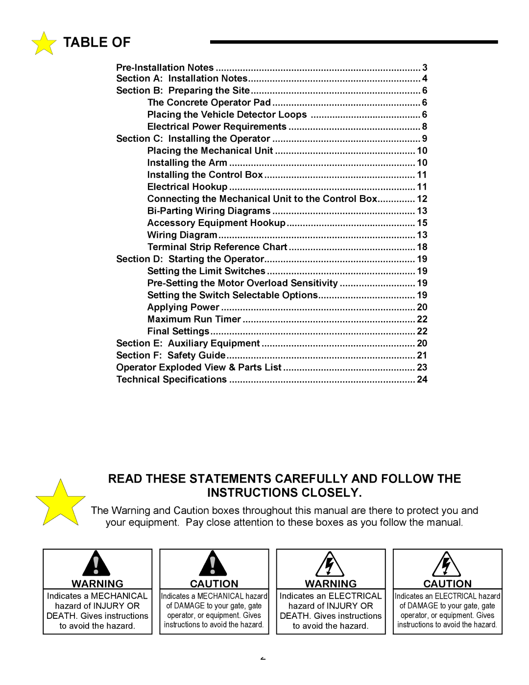
The Warning and Caution boxes throughout this manual are there to protect you and
your equipment. Pay close attention to these boxes as you follow the manual.
WARNING
Indicates a MECHANICAL
hazard of INJURY OR
DEATH. Gives instructions
to avoid the hazard.
CAUTION
Indicates a MECHANICAL hazard
of DAMAGE to your gate, gate operator, or equipment. Gives instructions to avoid the hazard.
WARNING
Indicates an ELECTRICAL
hazard of INJURY OR
DEATH. Gives instructions
to avoid the hazard.
CAUTION
Indicates an ELECTRICAL hazard of DAMAGE to your gate, gate operator, or equipment. Gives instructions to avoid the hazard.
2
