C: INSTALLING THE OPERATOR
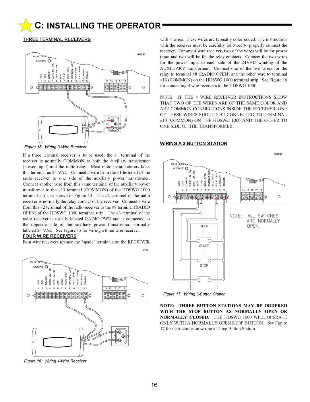
THREE TERMINAL RECEIVERS
104890
Figure 15: Wiring 3-Wire Receiver
If a three terminal receiver is to be used, the #1 terminal of the receiver is normally COMMON to both the auxiliary transformer (power input) and the radio relay. Most radio manufacturers label this terminal as 24 VAC. Connect a wire from the #1 terminal of the radio receiver to one side of the auxiliary power transformer. Connect another wire from this same terminal of the auxiliary power transformer to the #13 terminal (COMMON) of the HDSWG 1000 terminal strip, as shown in Figure 15. The #2 terminal of the radio receiver is normally the relay contact of the receiver. Connect a wire from this #2 terminal of the radio receiver to the #8 terminal (RADIO OPEN) of the HDSWG 1000 terminal strip. The #3 terminal of the radio receiver is usually labeled RADIO PWR and is connected to the opposite side of the auxiliary power transformer, normally labeled 24 VAC. See Figure 15 for wiring a three wire receiver.
FOUR WIRE RECEIVERS
Four wire receivers replace the "spade" terminals on the RECEIVER
104891
with 4 wires. These wires are typically color coded. The instructions with the receiver must be carefully followed to properly connect the receiver. For any 4 wire receiver, two of the wires will be for power input and two will be for the relay contacts. Connect the two wires for the power input to each side of the 24VAC winding of the AUXILIARY transformer. Connect one of the two wires for the relay to terminal #8 (RADIO OPEN) and the other wire to terminal #13 (COMMON) on the HDSWG 1000 terminal strip. See Figure 16 for connecting 4 wire receivers to the HDSWG 1000.
NOTE: IF THE 4 WIRE RECEIVER INSTRUCTIONS SHOW THAT TWO OF THE WIRES ARE OF THE SAME COLOR AND ARE COMMON CONNECTIONS INSIDE THE RECEIVER, ONE OF THESE WIRES SHOULD BE CONNECTED TO TERMINAL #13 (COMMON) ON THE HDSWG 1000 AND THE OTHER TO ONE SIDE OF THE TRANSFORMER.
WIRING A 3-BUTTON STATION
104892
Figure 17: Wiring 3-Button Station
NOTE: THREE BUTTON STATIONS MAY BE ORDERED WITH THE STOP BUTTON AS NORMALLY OPEN OR NORMALLY CLOSED. THE HDSWG 1000 WILL OPERATE ONLY WITH A NORMALLY OPEN STOP BUTTON. See Figure 17 for instructions on wiring a Three Button Station.
Figure 16: Wiring 4-Wire Receiver
16