Manuals
/
Altinex
/
Computer Equipment
/
Switch
Altinex
MT110-101
manual
Application Diagram, Diagram 1 Typical Setup
Models:
MT110-101
1
6
26
26
Download
26 pages
51.44 Kb
3
4
5
6
7
8
9
10
Troubleshooting
Specification
Install
Application Diagram
Warranty
Configuration
Description of Commands
SW Switch
Page 6
Image 6
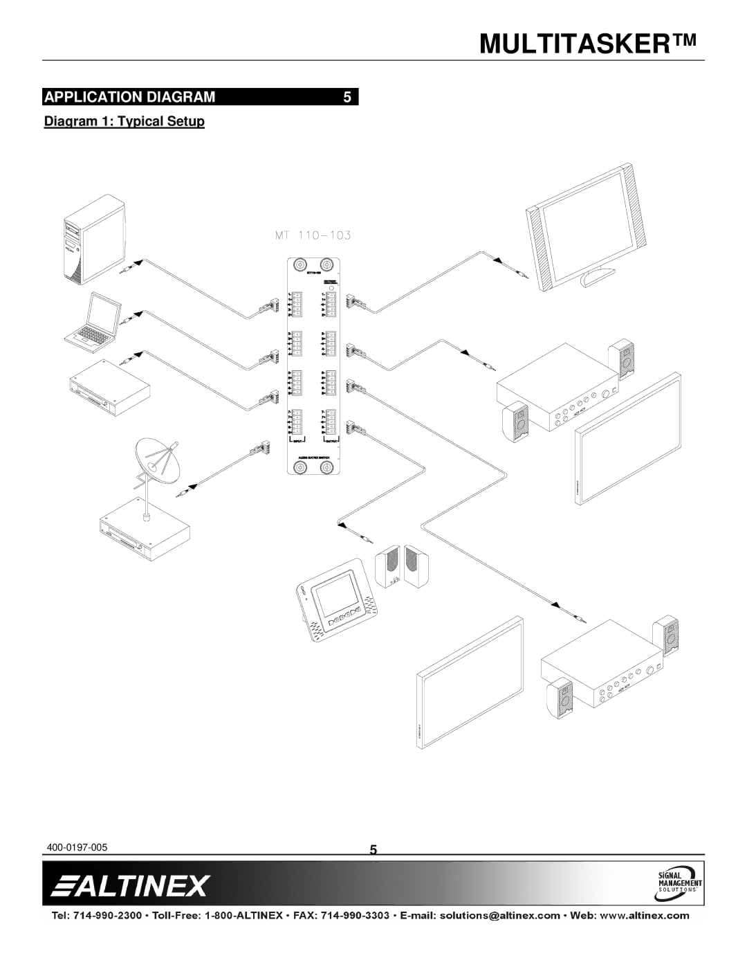
MULTITASKER™
APPLICATION DIAGRAM
5
Diagram 1: Typical Setup
400-0197-005
5
Page 5
Page 7
Page 6
Image 6
Page 5
Page 7
Contents
MT110-101/103
Table of Contents
Cleaning
Precautions / Safety Warnings
Installation
General
Technical Specifications
About Your MT110-101/103
Description of MT110-101/103
Application Diagram
Diagram 1 Typical Setup
Diagram 2 MT110-103 Internal View
Diagram 3 MT110-101 Internal View
Operation
Installing Your MT110-101/103
Description of Commands
RS-232 Control
VER
Configuration
Connection Output Volume
CnS
Saved
MT110-103 card
STA1
STA0
Group Operation
OFF
Path Operation
Feedback Operation
Single Card Operation
11. …F Feedback
SW Switch
10. …S Save
12. …P Path
OSO
CLR
OSI
FBD
RSI
SIDn
SIDnCi
RSN
Group Commands
SID+
25. WR
RMG
28. RD
Test
Volume Ramping Feature MT110-103 only
RUP MT110-103 only
Ramptime = 6 Seconds
Ramp Time = 16 Seconds
MATmXy
OSI
OFF
CLR
OSO
Troubleshooting Guide
No Sound
Distorted Sound
Sound Level is LOW
Limited WARRANTY/RETURN Policy
Altinex Policy
Toll Free 1-800-ALTINEX
Top
Page
Image
Contents