Manuals
/
Altinex
/
Computer Equipment
/
Switch
Altinex
MX2436RM 2. # SW n1 n2 n3 n4 n5 n6 - Audio Switch Input, 3. #RF - Factory Reset, Example
Models:
MX2436RM
1
11
15
15
Download
15 pages
16.27 Kb
8
9
10
11
12
13
14
15
Troubleshooting
Specifications
Install
Application Diagram
Warranty
Reset Mode
Accessories
Programming Commands
Switchers
Page 11
Image 11
Page 10
Page 12
Page 11
Image 11
Page 10
Page 12
Contents
MX2436RM
SWITCHERS
6-IN, 1-OUT COMPOSITE VIDEO AUDIO SWITCHER USER’S GUIDE
Page
TABLE OF CONTENTS
1.4 CLEANING
PRECAUTIONS / SAFETY WARNINGS
1.2 SAFETY GUIDELINES FOR THE RACK- MOUNTING OF THE MX2436RM
1.3 INSTALLATION
Audio
TECHNICAL SPECIFICATION
ABOUT YOUR MX2436RM
MX2436RM
DESCRIPTION OF MX2436RM
4.9. RESET MODE
4.4. AUTO SWITCH MODE
4.6 AUDIO VOLUME CONTROL
4.7. VERTICAL INTERVAL SWITCHING MODE
APPLICATION DIAGRAM
7.1 CONTROL PANEL
INSTALLING YOUR MX2436RM
OPERATION
PIN Designation
7.2 RS-232 CONTROL OF THE SWITCHER
PIN No
1. # SW n1 n2 n3 n4 n5 n6 - Video Switch Input
1. Square brackets ““ & “” are part of the command
2. Use uppercase letters for all commands
7.2.2 PROGRAMMING COMMANDS
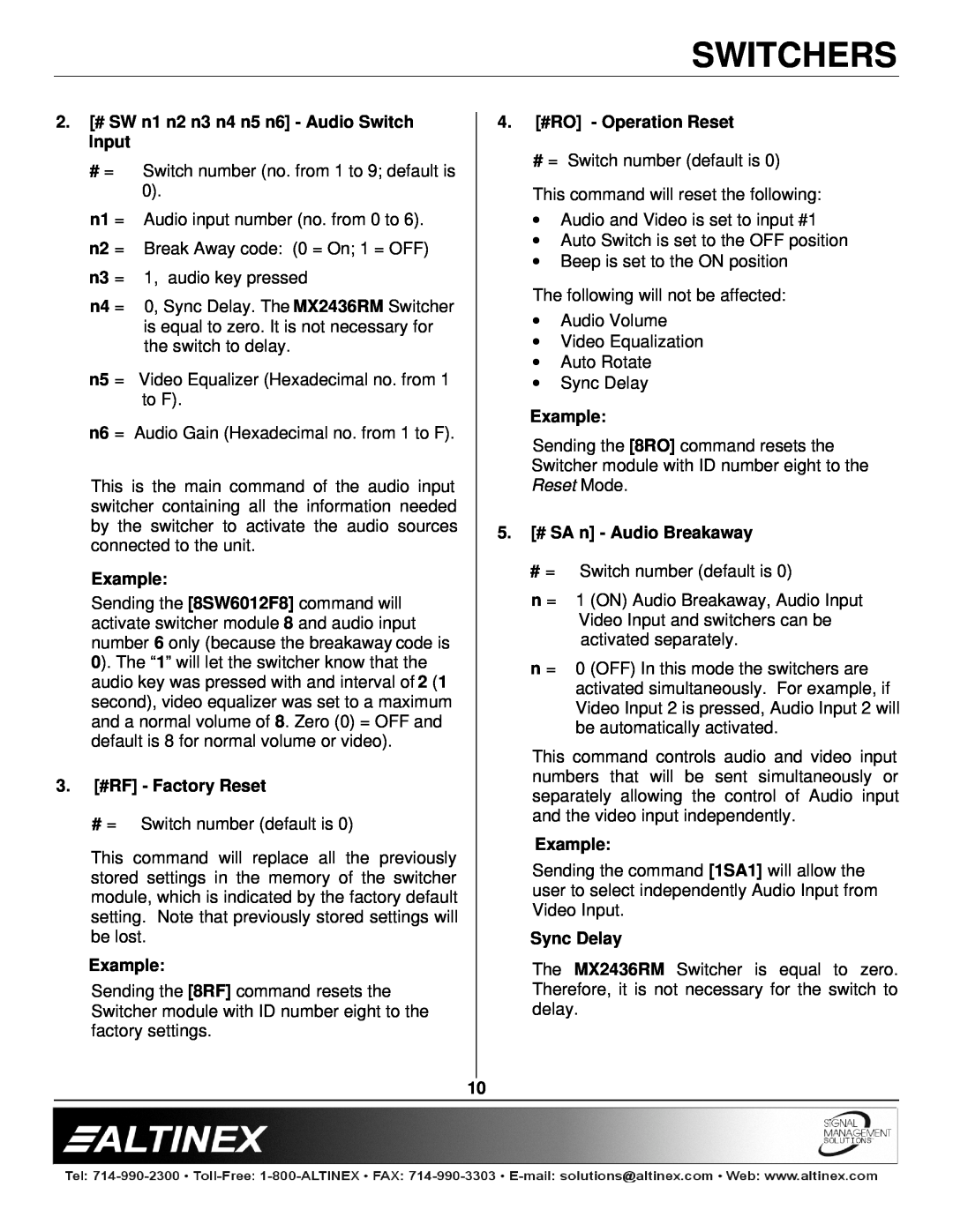
5. # SA n - Audio Breakaway
2. # SW n1 n2 n3 n4 n5 n6 - Audio Switch Input
3. #RF - Factory Reset
4. #RO - Operation Reset
8. 0I# - Change Identification Number
9. #CA n1 n2 - Audio Gain Control Save Settings
10. #CA n1 n2 - Video Equalization Save Settings
6. #Bn - Beep ON/OFF
4. #RO - Operation Reset 5. # SA n - Audio Breakaway
ACCESSORIES
7.2.3 SUMMARY OF COMMANDS
2. # SW n1 n2 n3 n4 n5 n6 - Audio Switch Input 3. #RF - Factory Reset
TROUBLESHOOTING GUIDE
FREQUENTLY ASKED QUESTIONS
11.3 CONTACT INFORMATION
11.1 LIMITED WARRANTY
ALTINEX POLICY
11.2 RETURN POLICY
Top
Page
Image
Contents