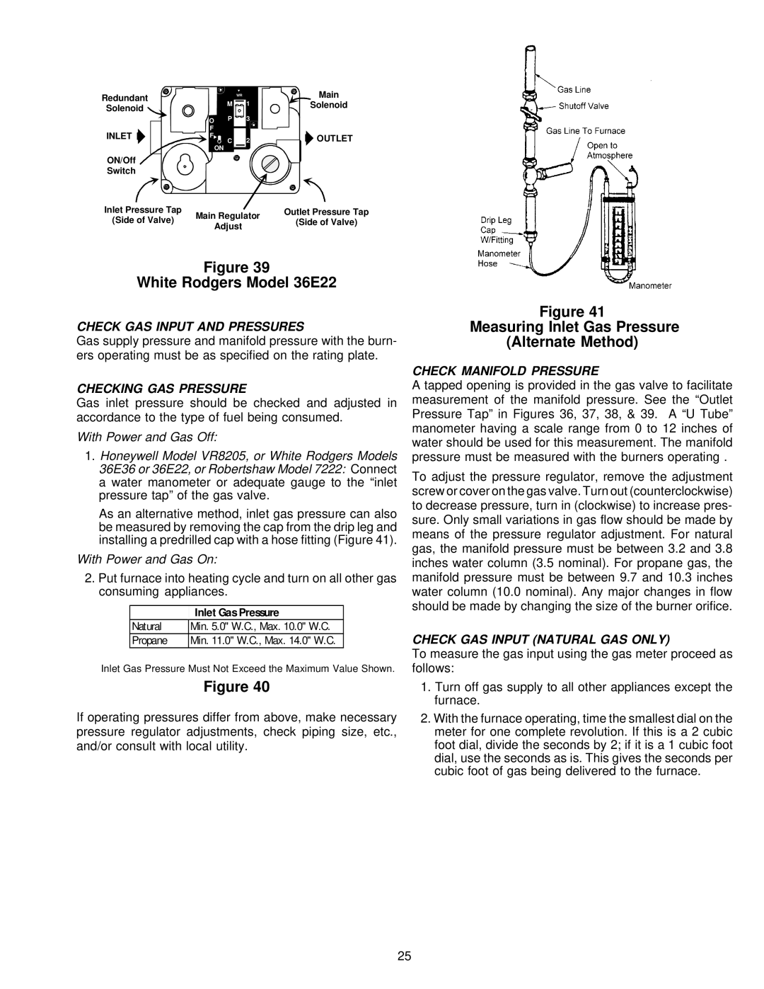
VR8205 specifications
The Amana VR8205 is a robust and innovative gas valve designed for use in a variety of heating applications, particularly in residential and commercial HVAC systems. This versatile valve offers a combination of advanced technologies and user-friendly features, making it a popular choice among HVAC professionals and system installers alike.One of the key features of the Amana VR8205 is its two-stage operation, allowing for precise control of gas flow. The dual-stage design enables the valve to modulate the gas supply based on the heating demand, which enhances system efficiency and promotes better temperature regulation. This feature not only contributes to energy savings but also helps maintain a comfortable indoor environment.
Additionally, the VR8205 is equipped with a strong, durable body construction that ensures reliability and longevity. Designed to withstand harsh operating conditions, the valve’s materials are resistant to corrosion and wear, making it suitable for various applications. The robust design of the Amana VR8205 minimizes the likelihood of leaks or failures, providing peace of mind to both installers and end-users.
The valve operates on low voltage, typically requiring 24 volts, which makes it energy-efficient and compatible with most modern thermostatic control systems. This low-voltage operation also simplifies installation, as it reduces the complexity and requirements for the electrical setup.
Another noteworthy characteristic of the Amana VR8205 is its integrated safety features. It includes a combination of automatic and manual shut-off mechanisms, providing an added layer of safety in case of malfunctions. This ensures that the gas supply can be quickly halted in emergency situations, protecting both people and property.
Moreover, the Amana VR8205 is designed for easy maintenance, featuring simple access points for servicing and troubleshooting. This ease of maintenance is crucial for HVAC professionals, as it allows for quick adjustments and repairs, ultimately reducing downtime.
Lastly, the Amana VR8205 has a reputation for adaptability, being compatible with various heating appliances, including furnaces, boilers, and water heaters. Its versatility makes it an excellent solution for a wide range of heating applications, ensuring optimal performance across different systems.
In summary, the Amana VR8205 gas valve is characterized by its two-stage operation, durable construction, low-voltage functionality, integrated safety mechanisms, and ease of maintenance. These features combine to offer a reliable, efficient, and flexible solution for modern heating needs.

