Step 10 Connect I/O
Onboard Adapters The Pegasus PCI motherboard has:
∙two serial ports (J2 and J3),
∙a parallel port (J8),
∙an IDE controller on the PCI bus (the primary IDE connector is J11 and the secondary IDE connector is J9), and
∙a floppy controller (J4).
The serial and parallel port connectors are described below.
Conflicts AMIBIOS minimizes conflicts between onboard and offboard I/O devices.
AMIBIOS automatically checks the adapter cards installed in the expansion slots on the Pegasus PCI motherboard for a hard disk or floppy controller and serial or parallel ports.
J3 SER1 J2 SER2 J2 and J3 are
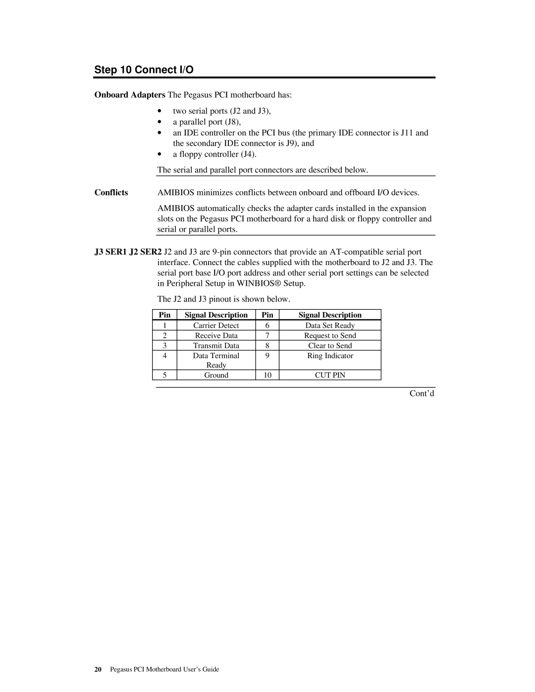
The J2 and J3 pinout is shown below.
Pin | Signal Description | Pin | Signal Description |
1 | Carrier Detect | 6 | Data Set Ready |
2 | Receive Data | 7 | Request to Send |
3 | Transmit Data | 8 | Clear to Send |
4 | Data Terminal | 9 | Ring Indicator |
| Ready |
|
|
5 | Ground | 10 | CUT PIN |
Cont’d
20Pegasus PCI Motherboard User’s Guide