Step 10 Connect I/O, Continued
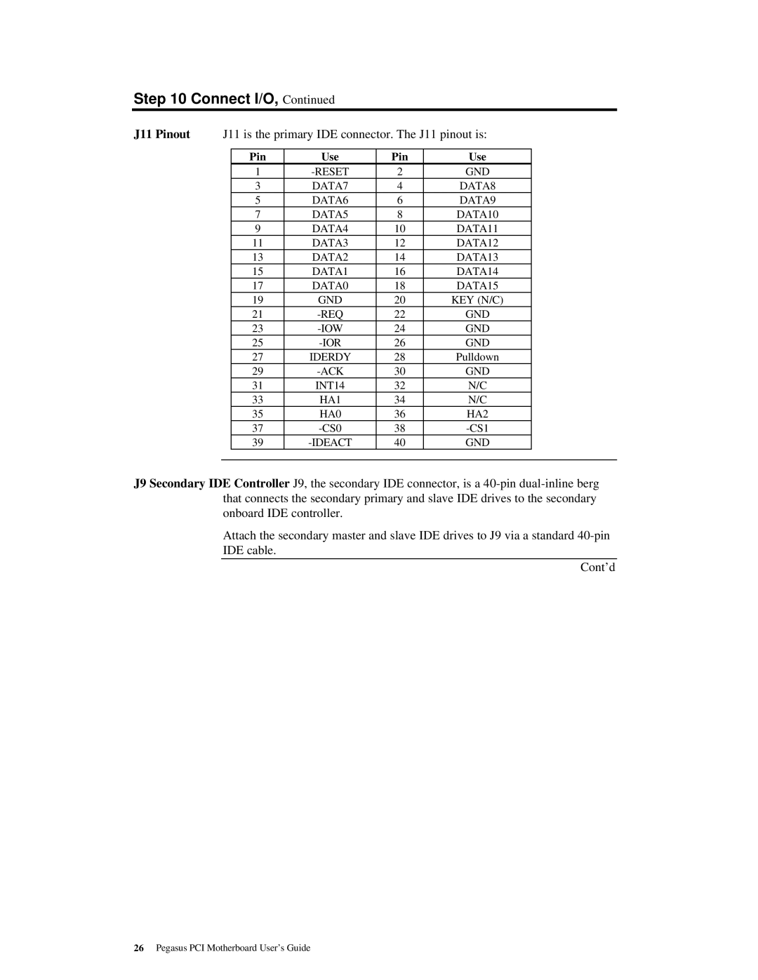
J11 Pinout J11 is the primary IDE connector. The J11 pinout is:
| Pin | Use | Pin | Use |
|
| 1 |
| 2 | GND |
|
| 3 | DATA7 | 4 | DATA8 |
|
| 5 | DATA6 | 6 | DATA9 |
|
| 7 | DATA5 | 8 | DATA10 |
|
| 9 | DATA4 | 10 | DATA11 |
|
| 11 | DATA3 | 12 | DATA12 |
|
| 13 | DATA2 | 14 | DATA13 |
|
| 15 | DATA1 | 16 | DATA14 |
|
| 17 | DATA0 | 18 | DATA15 |
|
| 19 | GND | 20 | KEY (N/C) |
|
| 21 |
| 22 | GND |
|
| 23 | 24 | GND |
| |
| 25 | 26 | GND |
| |
| 27 | IDERDY | 28 | Pulldown |
|
| 29 | 30 | GND |
| |
| 31 | INT14 | 32 | N/C |
|
| 33 | HA1 | 34 | N/C |
|
| 35 | HA0 | 36 | HA2 |
|
| 37 | 38 |
| ||
| 39 | 40 | GND |
| |
|
|
|
|
|
|
J9 Secondary IDE Controller J9, the secondary IDE connector, is a
Attach the secondary master and slave IDE drives to J9 via a standard
Cont’d
26Pegasus PCI Motherboard User’s Guide