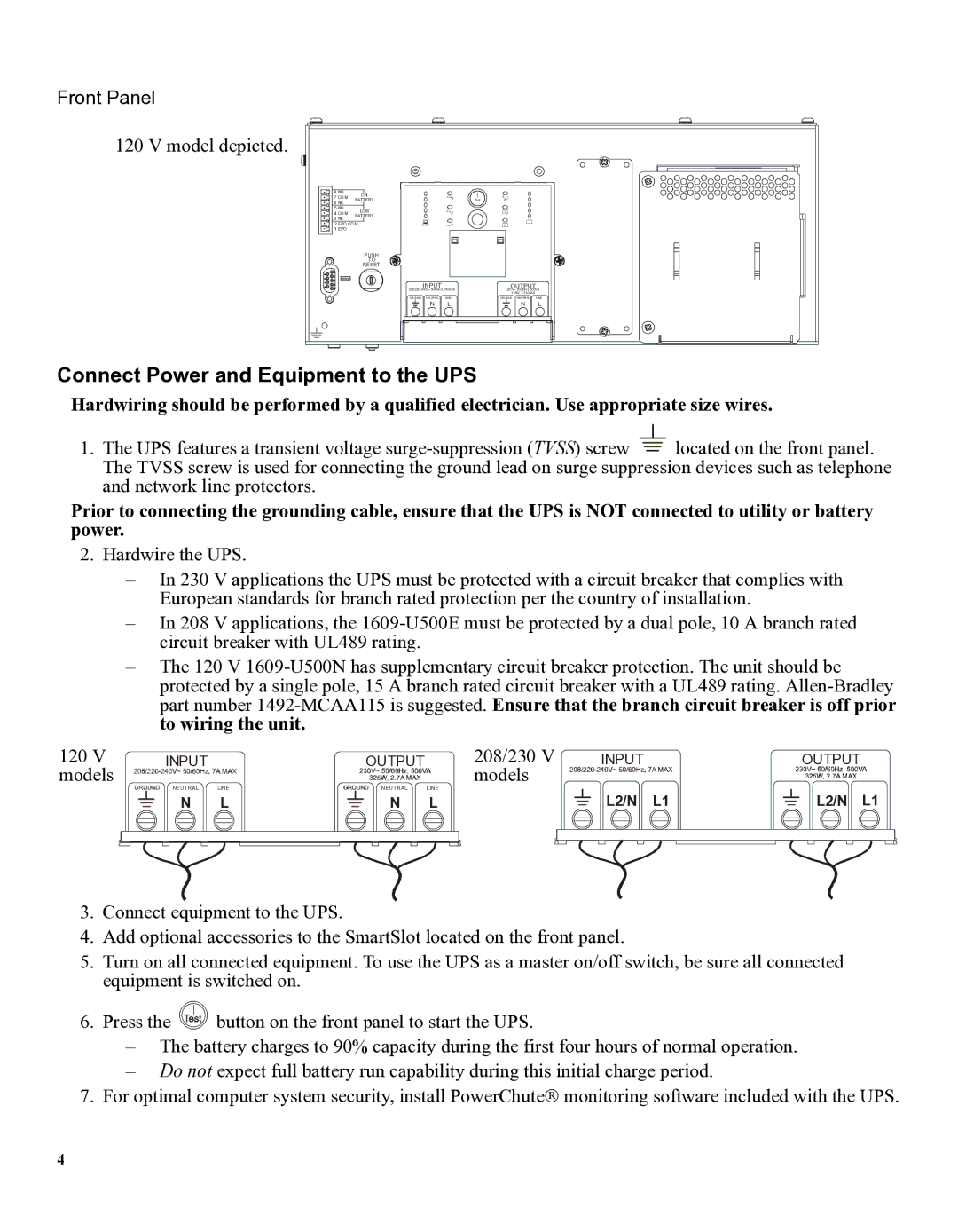
Front Panel
120 V model depicted.
8 NO | ON |
| |
7 COM | BATTERY | Test | |
6 NC | |||
|
| ||
5 NO | LOW |
| |
4 COM | BATTERY |
| |
3 NC |
| ||
|
| ||
2 EPO COM |
| ||
1 EPO |
|
| |
PUSH
TO
RESET
INPUT |
| OUTPUT |
|
230V~ 50/60Hz, 500VA | |||
|
| 325W, 2.7A MAX |
|
GROUND NEUTRAL | LINE | GROUND NEUTRAL | LINE |
N | L | N | L |
Connect Power and Equipment to the UPS
Hardwiring should be performed by a qualified electrician. Use appropriate size wires.
1.The UPS features a transient voltage ![]() located on the front panel. The TVSS screw is used for connecting the ground lead on surge suppression devices such as telephone and network line protectors.
located on the front panel. The TVSS screw is used for connecting the ground lead on surge suppression devices such as telephone and network line protectors.
Prior to connecting the grounding cable, ensure that the UPS is NOT connected to utility or battery power.
2.Hardwire the UPS.
–In 230 V applications the UPS must be protected with a circuit breaker that complies with European standards for branch rated protection per the country of installation.
–In 208 V applications, the
–The 120 V
120 V | INPUT |
| OUTPUT | 208/230 V | INPUT | OUTPUT |
models |
|
|
| models |
|
|
| NEUTRAL | LINE | NEUTRAL | LINE | L2/N L1 | L2/N L1 |
| N | L | N | L |
3.Connect equipment to the UPS.
4.Add optional accessories to the SmartSlot located on the front panel.
5.Turn on all connected equipment. To use the UPS as a master on/off switch, be sure all connected equipment is switched on.
6.Press the ![]() button on the front panel to start the UPS.
button on the front panel to start the UPS.
–The battery charges to 90% capacity during the first four hours of normal operation.
–Do not expect full battery run capability during this initial charge period.
7.For optimal computer system security, install PowerChute monitoring software included with the UPS.
4
