Contact Sensors, continued
Sensor zone description
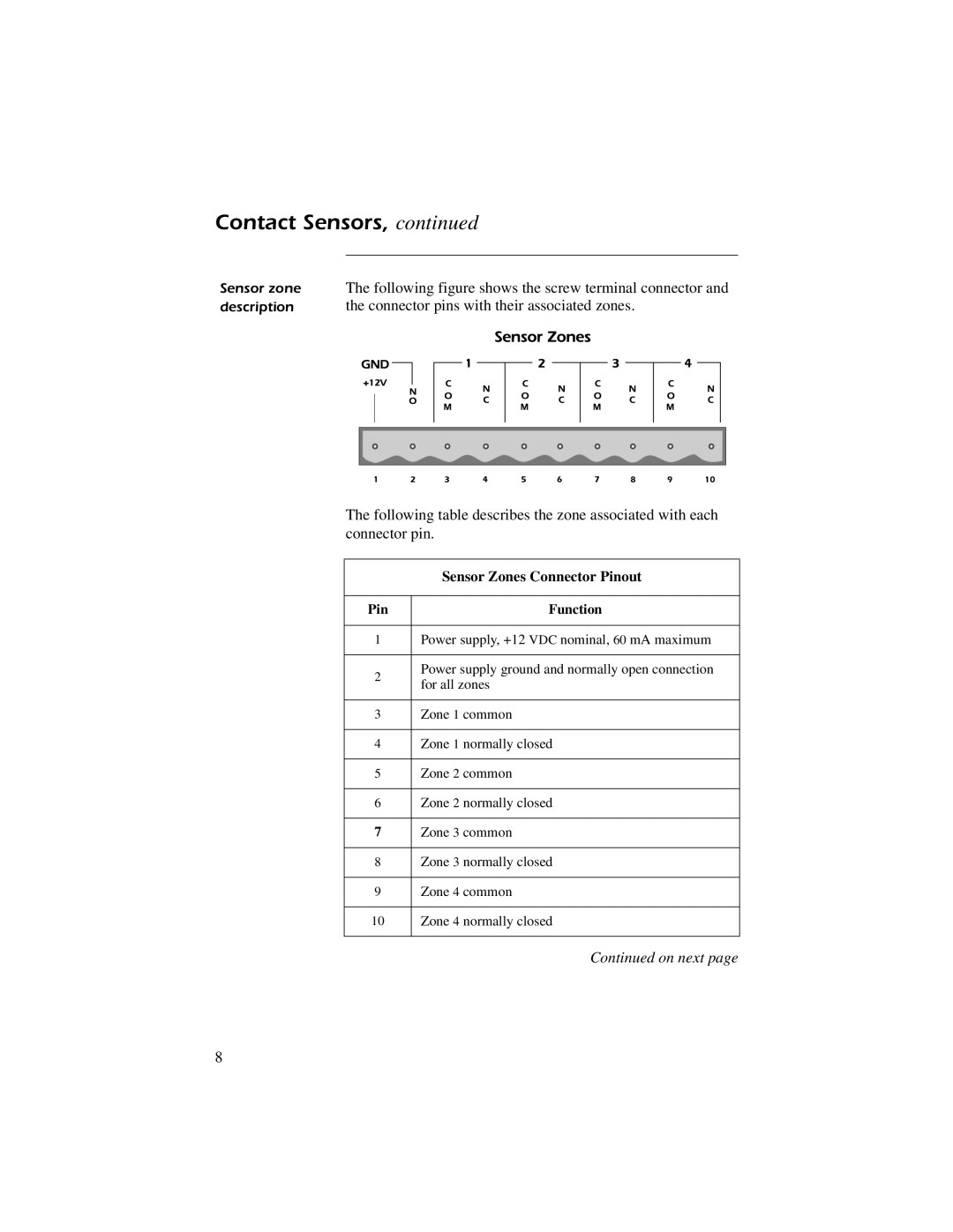
The following figure shows the screw terminal connector and the connector pins with their associated zones.
The following table describes the zone associated with each connector pin.
| Sensor Zones Connector Pinout | |
|
| |
Pin | Function | |
|
| |
1 | Power supply, +12 VDC nominal, 60 mA maximum | |
|
| |
2 | Power supply ground and normally open connection | |
for all zones | ||
| ||
|
| |
3 | Zone 1 common | |
|
| |
4 | Zone 1 normally closed | |
|
| |
5 | Zone 2 common | |
|
| |
6 | Zone 2 normally closed | |
|
| |
7 | Zone 3 common | |
|
| |
8 | Zone 3 normally closed | |
|
| |
9 | Zone 4 common | |
|
| |
10 | Zone 4 normally closed | |
|
|
Continued on next page
8
