| E | E |
|
Electricity | N | N | Load |
Board | L | L | |
Meter |
| ||
|
|
| |
| Switch Lighting |
|
|
| Circuit |
|
|
| Input | Output |
|
| Wiring for Power Inverter |
| |
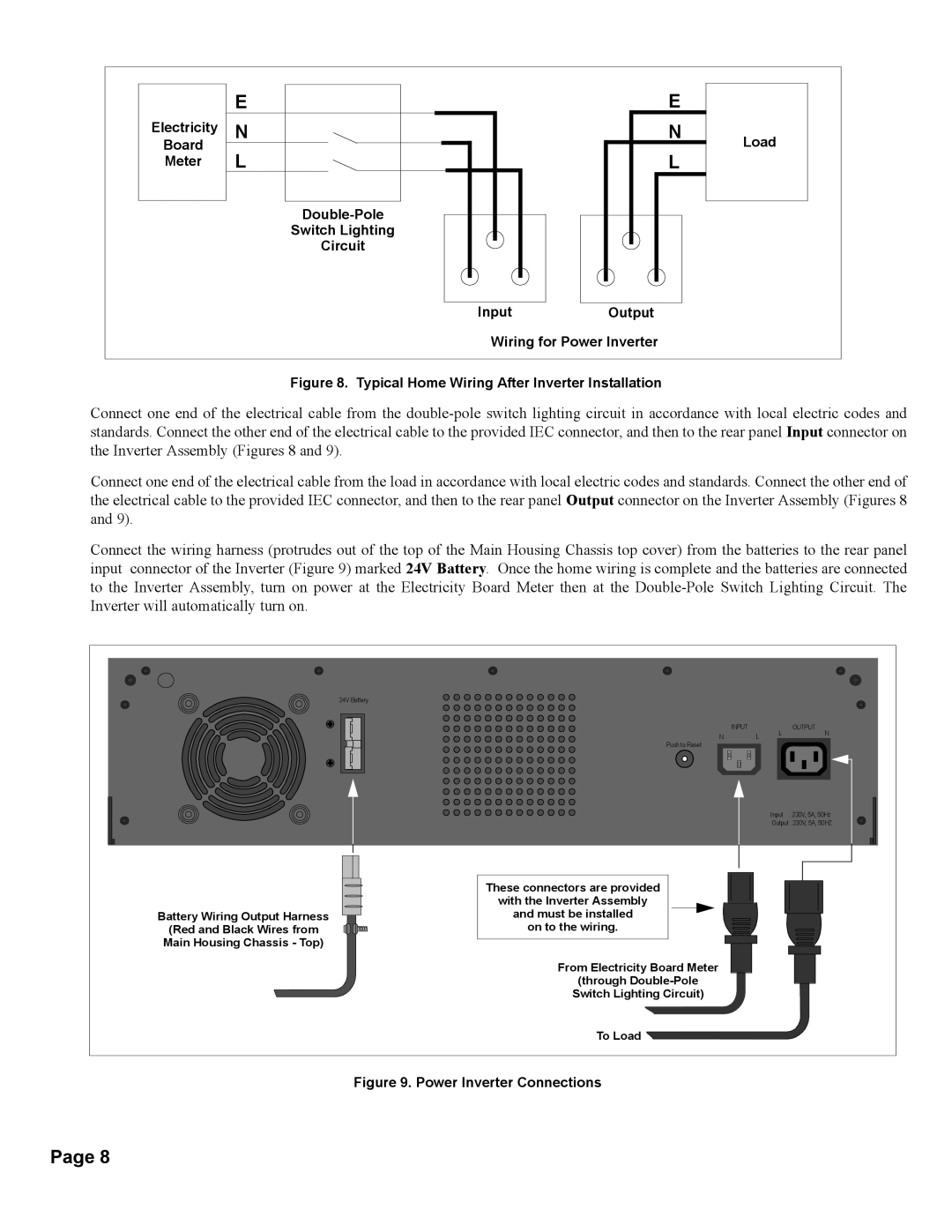
Figure 8. Typical Home Wiring After Inverter Installation
Connect one end of the electrical cable from the
Connect one end of the electrical cable from the load in accordance with local electric codes and standards. Connect the other end of the electrical cable to the provided IEC connector, and then to the rear panel Output connector on the Inverter Assembly (Figures 8 and 9).
Connect the wiring harness (protrudes out of the top of the Main Housing Chassis top cover) from the batteries to the rear panel input connector of the Inverter (Figure 9) marked 24V Battery. Once the home wiring is complete and the batteries are connected to the Inverter Assembly, turn on power at the Electricity Board Meter then at the
24V Battery
| INPUT | L | OUTPUT |
N | L | N |
Push to Reset
Input : 230V, 5A, 50Hz
Output : 230V, 5A, 50HZ
Battery Wiring Output Harness
(Red and Black Wires from
Main Housing Chassis - Top)
These connectors are provided
with the Inverter Assembly
and must be installed
on to the wiring.
From Electricity Board Meter
(through
Switch Lighting Circuit)
To Load
Figure 9. Power Inverter Connections
Page 8