Main Housing Chassis |
| Main Housing Chassis | |
(top cover not shown) |
| (top cover shown) | |
Battery | Battery |
| |
Handle | Handle | Red (+) | |
| Positive | ||
Negative | Wire | ||
(+) |
| ||
| |||
Terminal |
| ||
Terminal | Positive (+) | ||
| |||
First | Negative | Terminal | |
| |||
Battery | Terminal |
| |
| Black |
| |
|
| ||
| Wire | Black | |
|
| Wire | |
Battery | Battery |
| |
Handle | Handle | Negative | |
|
| Terminal | |
| Positive |
| |
| (+) |
| |
| Terminal |
| |
Second Battery |
| Main Housing Chassis | |
(rotated 180 degrees) |
| ||
| (rotated 180 degrees) | ||
|
| ||
Battery Installation |
| Battery Connections |
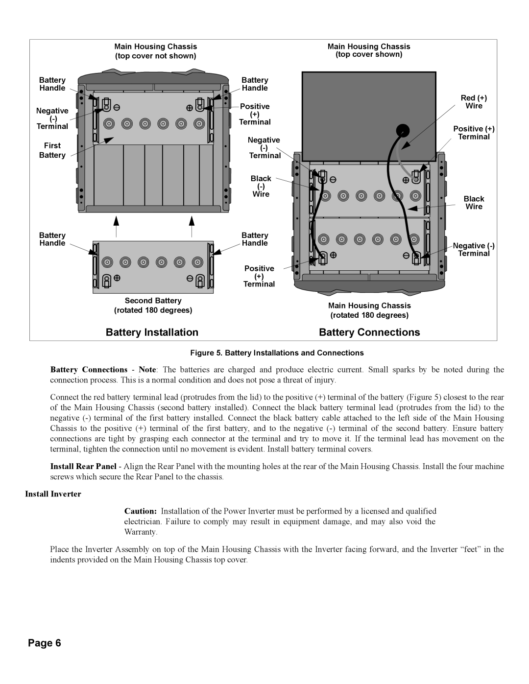
Figure 5. Battery Installations and Connections
Battery Connections - Note: The batteries are charged and produce electric current. Small sparks by be noted during the connection process. This is a normal condition and does not pose a threat of injury.
Connect the red battery terminal lead (protrudes from the lid) to the positive (+) terminal of the battery (Figure 5) closest to the rear of the Main Housing Chassis (second battery installed). Connect the black battery terminal lead (protrudes from the lid) to the negative
Install Rear Panel - Align the Rear Panel with the mounting holes at the rear of the Main Housing Chassis. Install the four machine screws which secure the Rear Panel to the chassis.
Install Inverter
Caution: Installation of the Power Inverter must be performed by a licensed and qualified electrician. Failure to comply may result in equipment damage, and may also void the Warranty.
Place the Inverter Assembly on top of the Main Housing Chassis with the Inverter facing forward, and the Inverter “feet” in the indents provided on the Main Housing Chassis top cover.
Page 6
