Install Wiring Management Kit
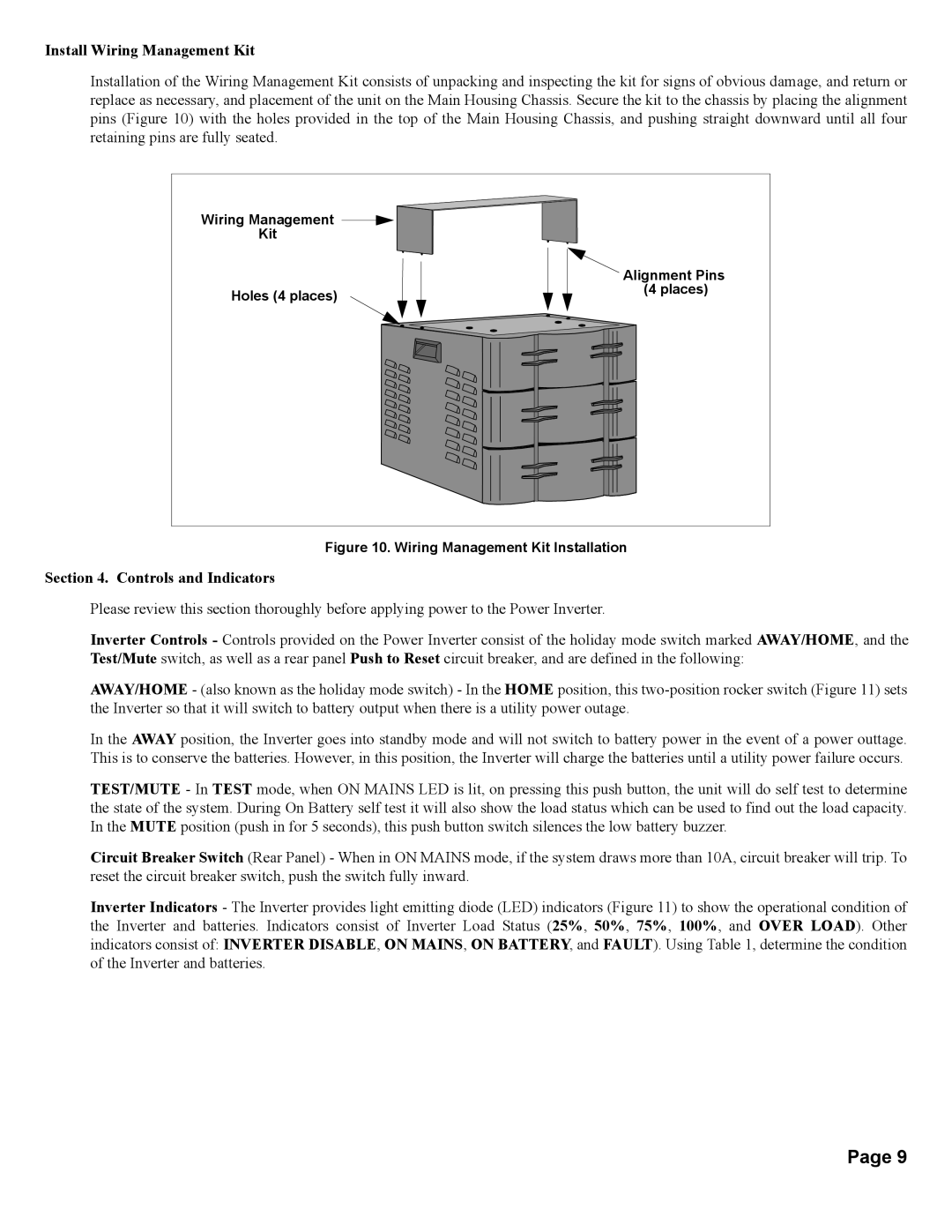
Installation of the Wiring Management Kit consists of unpacking and inspecting the kit for signs of obvious damage, and return or replace as necessary, and placement of the unit on the Main Housing Chassis. Secure the kit to the chassis by placing the alignment pins (Figure 10) with the holes provided in the top of the Main Housing Chassis, and pushing straight downward until all four retaining pins are fully seated.
Wiring Management |
|
Kit |
|
| Alignment Pins |
Holes (4 places) | (4 places) |
|
Figure 10. Wiring Management Kit Installation
Section 4. Controls and Indicators
Please review this section thoroughly before applying power to the Power Inverter.
Inverter Controls - Controls provided on the Power Inverter consist of the holiday mode switch marked AWAY/HOME, and the Test/Mute switch, as well as a rear panel Push to Reset circuit breaker, and are defined in the following:
AWAY/HOME - (also known as the holiday mode switch) - In the HOME position, this
In the AWAY position, the Inverter goes into standby mode and will not switch to battery power in the event of a power outtage. This is to conserve the batteries. However, in this position, the Inverter will charge the batteries until a utility power failure occurs.
TEST/MUTE - In TEST mode, when ON MAINS LED is lit, on pressing this push button, the unit will do self test to determine the state of the system. During On Battery self test it will also show the load status which can be used to find out the load capacity. In the MUTE position (push in for 5 seconds), this push button switch silences the low battery buzzer.
Circuit Breaker Switch (Rear Panel) - When in ON MAINS mode, if the system draws more than 10A, circuit breaker will trip. To reset the circuit breaker switch, push the switch fully inward.
Inverter Indicators - The Inverter provides light emitting diode (LED) indicators (Figure 11) to show the operational condition of the Inverter and batteries. Indicators consist of Inverter Load Status (25%, 50%, 75%, 100%, and OVER LOAD). Other indicators consist of: INVERTER DISABLE, ON MAINS, ON BATTERY, and FAULT). Using Table 1, determine the condition of the Inverter and batteries.
Page 9
