Models 2603, 2621, and 2635 Getting Started Guide | 3 • Initial Configuration |
|
|
4.
The interface cable has been installed, go to section “Installing the AC power cord” on page 34.
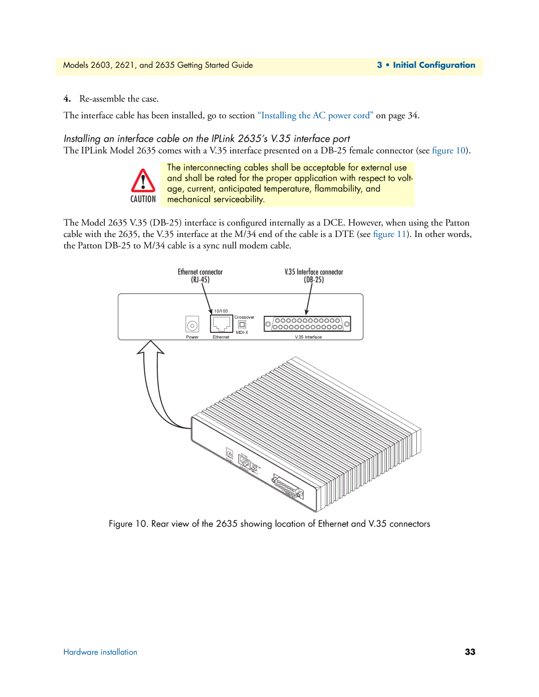
Installing an interface cable on the IPLink 2635’s V.35 interface port
The IPLink Model 2635 comes with a V.35 interface presented on a
The interconnecting cables shall be acceptable for external use
and shall be rated for the proper application with respect to volt-
age, current, anticipated temperature, flammability, and
CAUTION mechanical serviceability.
The Model 2635 V.35
Ethernet connector | V.35 Interface connector | |
|
|
|
| 10/100 |
|
|
| Crossover |
Power | Ethernet | |
V.35 Interface | ||
Power | 10/100 |
|
| Crossover | |
| Ethernet | |
| MDI- | |
|
| |
|
| X |
X. |
|
21 |
|
WAN | |
| Interface |
Figure 10. Rear view of the 2635 showing location of Ethernet and V.35 connectors
Hardware installation | 33 |