Optional Equipment Installation
Galvanic Isolation Transformer
The galvanic isolation transformer can be delivered for one- or
Note:
If the cables in the galvanic isolation transformer have 4 wires, the wire marked no. 3 must be cut off.
Galvanic Isolation Transformer Connections
The AC bus from the galvanic isolation transformer must be mounted.
Note:
If the galvanic isolation module is installed it must be secured so that the neutral is grounded according to local regulations.
This is done in the galvanic isolation transformer with a wire between terminal 5 (PE) and 9 (neutral).
This wire is already mounted from the factory. If the
to terminal 9, after having removed the wire between terminals 5 and 9.
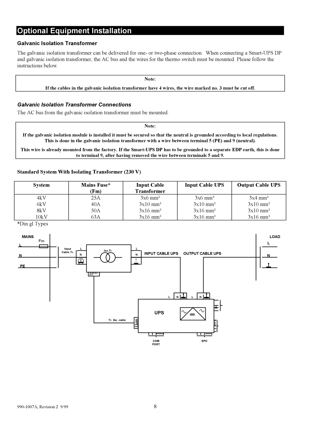
Standard System With Isolating Transformer (230 V)
System | Mains Fuse* | Input Cable | Input Cable UPS | Output Cable UPS |
| (Fm) | Transformer |
|
|
4kV | 25A | 3x6 mm² | 3x6 mm² | 3x4 mm² |
6kV | 40A | 3x10 mm² | 3x10 mm² | 3x10 mm² |
8kV | 50A | 3x16 mm² | 3x16 mm² | 3x10 mm² |
10kV | 63A | 3x16 mm² | 3x16 mm² | 3x16 mm² |
*Din gl Types
MAINS
Fm
L
N
PE
Input L
Cable Tr.
N
Iso.Tr | L | |
N INPUT CABLE UPS OUTPUT CABLE UPS | ||
. |
L | N | L | N |
UPS
Tr. Sw. cable
LOAD L
N
COM | EPO |
PORT |
|
| 8 |