MAINS
LFm
N
PE
INPUT | L |
| SBP |
|
CABLE |
|
|
| |
SBP | N |
|
|
|
| X010 |
|
| |
| 1 2 | 3 | 4 |
|
| SBP |
| Input | Output |
| CABLE |
| cable | |
|
| cable | ||
|
|
| UPS | |
|
|
| UPS | |
|
|
|
| |
|
|
| L N | L N |
| 1 2 | 3 | 4 |
|
| MBS CONTROL |
| ||
UPS
L
N
OUTPUT CABLE SBP
LOAD
Fo L
N
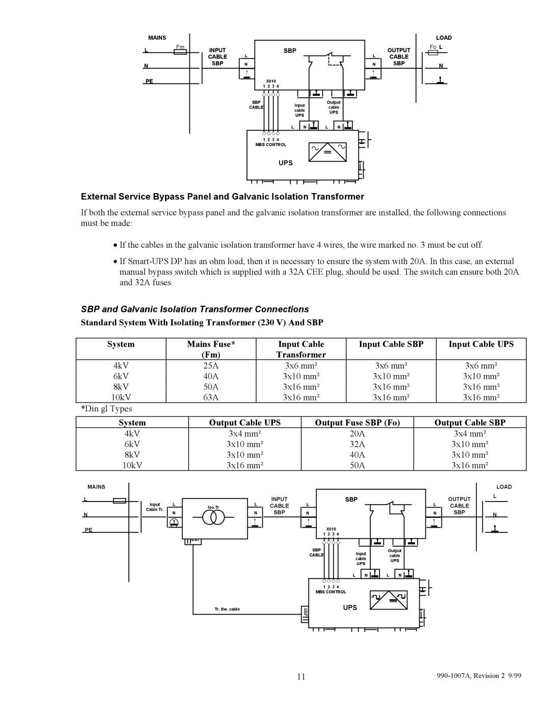
External Service Bypass Panel and Galvanic Isolation Transformer
If both the external service bypass panel and the galvanic isolation transformer are installed, the following connections must be made:
•If the cables in the galvanic isolation transformer have 4 wires, the wire marked no. 3 must be cut off.
•If
SBP and Galvanic Isolation Transformer Connections
Standard System With Isolating Transformer (230 V) And SBP
System | Mains Fuse* | Input Cable | Input Cable SBP | Input Cable UPS |
| (Fm) | Transformer |
|
|
4kV | 25A | 3x6 mm² | 3x6 mm² | 3x6 mm² |
6kV | 40A | 3x10 mm² | 3x10 mm² | 3x10 mm² |
8kV | 50A | 3x16 mm² | 3x16 mm² | 3x16 mm² |
10kV | 63A | 3x16 mm² | 3x16 mm² | 3x16 mm² |
*Din gl Types
System | Output Cable UPS | Output Fuse SBP (Fo) | Output Cable SBP |
4kV | 3x4 mm² | 20A | 3x4 mm² |
6kV | 3x10 mm² | 32A | 3x10 mm² |
8kV | 3x10 mm² | 40A | 3x10 mm² |
10kV | 3x16 mm² | 50A | 3x16 mm² |
MAINS
L
N
PE
Input L
Cable Tr.
N
Iso.Tr
.
Tr. Sw. cable
L
N
INPUT | L |
| SBP |
|
CABLE |
|
|
| |
SBP | N |
|
|
|
| X010 |
|
| |
| 1 2 | 3 | 4 |
|
| SBP |
| Input | Output |
| CABLE |
| cable | |
|
|
| cable | UPS |
|
|
| UPS | |
|
|
|
| |
|
|
| L N | L N |
| 1 2 | 3 | 4 |
|
| MBS CONTROL |
| ||
UPS
L
N
OUTPUT CABLE SBP
LOAD L
N
11 |
