Placement
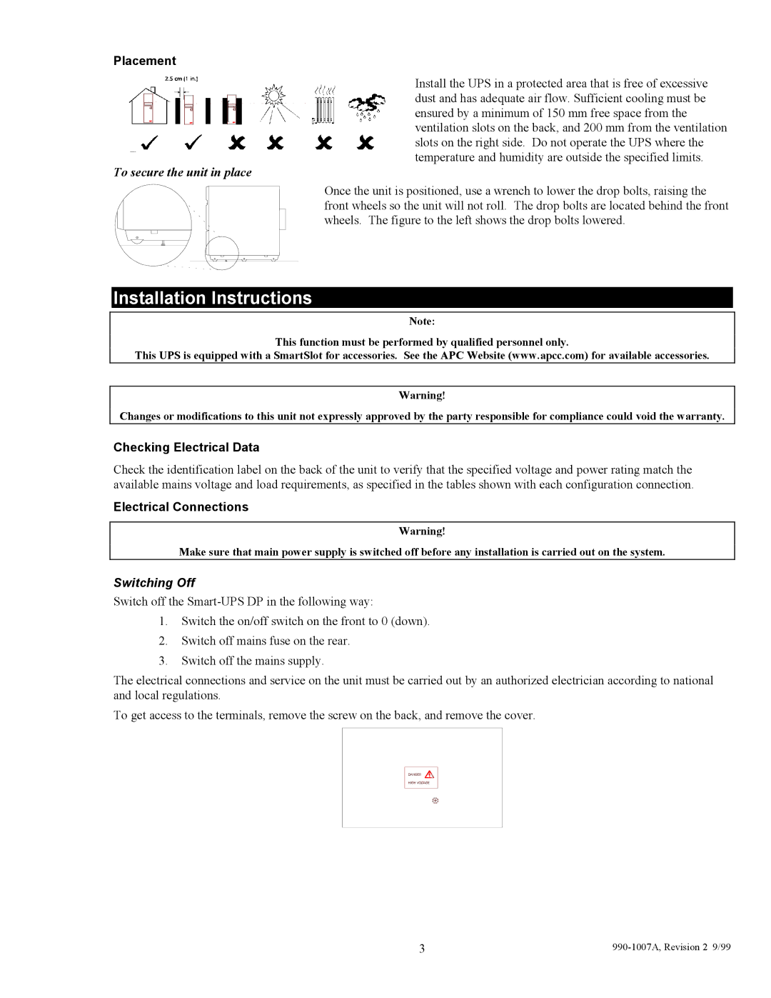
Install the UPS in a protected area that is free of excessive dust and has adequate air flow. Sufficient cooling must be ensured by a minimum of 150 mm free space from the ventilation slots on the back, and 200 mm from the ventilation slots on the right side. Do not operate the UPS where the temperature and humidity are outside the specified limits.
To secure the unit in place
Once the unit is positioned, use a wrench to lower the drop bolts, raising the front wheels so the unit will not roll. The drop bolts are located behind the front wheels. The figure to the left shows the drop bolts lowered.
Installation Instructions
Note:
This function must be performed by qualified personnel only.
This UPS is equipped with a SmartSlot for accessories. See the APC Website (www.apcc.com) for available accessories.
Warning!
Changes or modifications to this unit not expressly approved by the party responsible for compliance could void the warranty.
Checking Electrical Data
Check the identification label on the back of the unit to verify that the specified voltage and power rating match the available mains voltage and load requirements, as specified in the tables shown with each configuration connection.
Electrical Connections
Warning!
Make sure that main power supply is switched off before any installation is carried out on the system.
Switching Off
Switch off the
1.Switch the on/off switch on the front to 0 (down).
2.Switch off mains fuse on the rear.
3.Switch off the mains supply.
The electrical connections and service on the unit must be carried out by an authorized electrician according to national and local regulations.
To get access to the terminals, remove the screw on the back, and remove the cover.
DANGER
HIGH VOLTAGE
3 |
