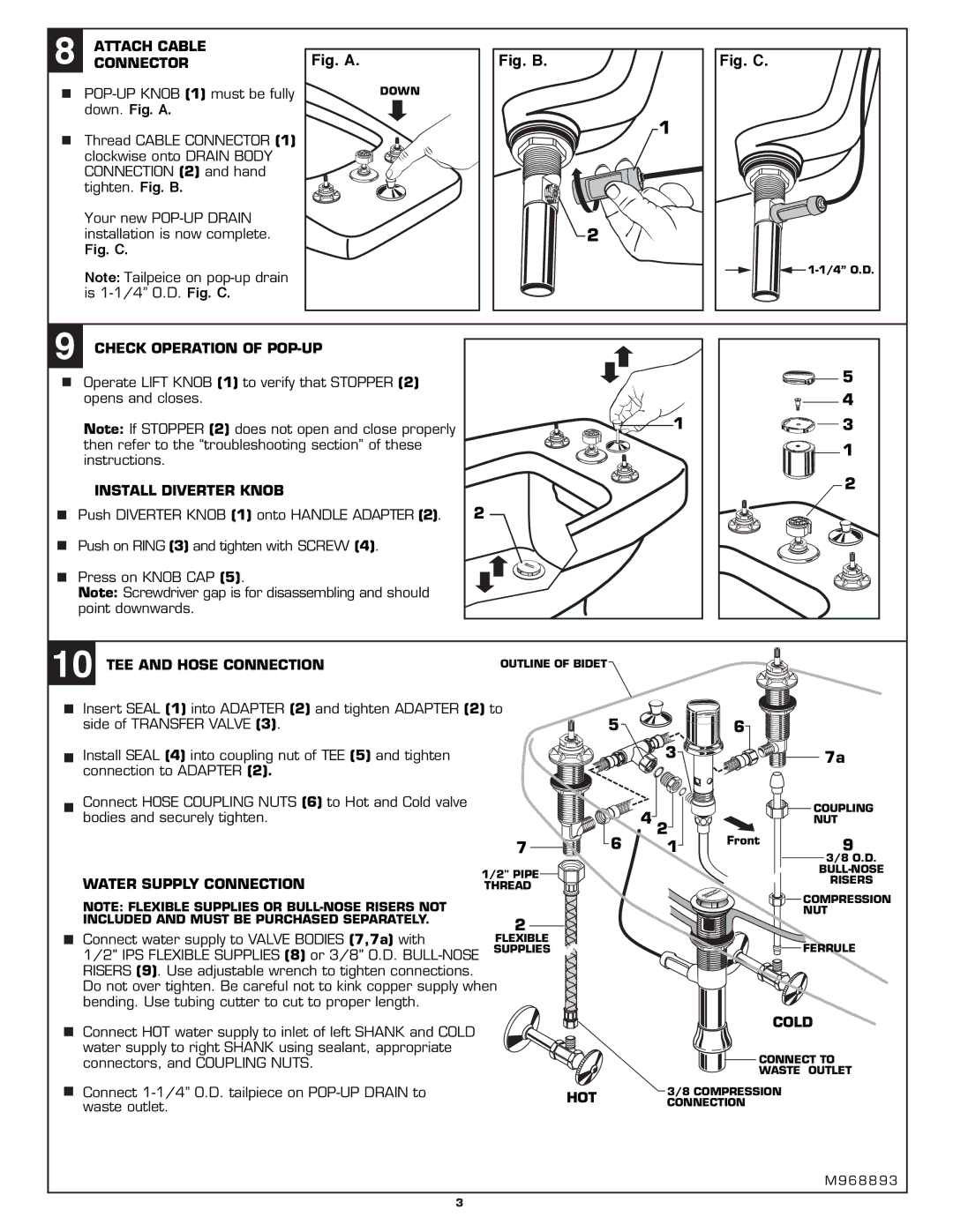
8 ATTACH CABLE CONNECTOR
Thread CABLE CONNECTOR (1) clockwise onto DRAIN BODY CONNECTION (2) and hand tighten. Fig. B.
Your new
Fig. C.
Note: Tailpeice on
Fig. A.
DOWN
Fig. B.
1
![]() 2
2
Fig. C.
![]()
9 CHECK OPERATION OF POP-UP
Operate LIFT KNOB (1) to verify that STOPPER (2) opens and closes.
Note: If STOPPER (2) does not open and close properly then refer to the “troubleshooting section” of these instructions.
INSTALL DIVERTER KNOB
Push DIVERTER KNOB (1) onto HANDLE ADAPTER (2).
Push on RING (3) and tighten with SCREW (4).
Press on KNOB CAP (5).
Note: Screwdriver gap is for disassembling and should point downwards.
1
2
5
4
![]()
![]() 3
3
1 2
10 TEE AND HOSE CONNECTION
OUTLINE OF BIDET
Insert SEAL (1) into ADAPTER (2) and tighten ADAPTER (2) to side of TRANSFER VALVE (3).
Install SEAL (4) into coupling nut of TEE (5) and tighten connection to ADAPTER (2).
Connect HOSE COUPLING NUTS (6) to Hot and Cold valve bodies and securely tighten.
WATER SUPPLY CONNECTION
NOTE: FLEXIBLE SUPPLIES OR
Connect water supply to VALVE BODIES (7,7a) with
1/2" IPS FLEXIBLE SUPPLIES (8) or 3/8" O.D.
Connect HOT water supply to inlet of left SHANK and COLD water supply to right SHANK using sealant, appropriate connectors, and COUPLING NUTS.
Connect
5![]()
![]() 6
6
| 3 |
| 7a |
| 4 2 |
| COUPLING |
|
| NUT | |
|
|
| |
6 | 1 | Front | 9 |
| |||
|
|
| 3/8 O.D. |
|
|
| |
|
|
| RISERS |
|
|
| COMPRESSION |
|
|
| NUT |
|
|
| FERRULE |
COLD
![]()
![]() CONNECT TO
CONNECT TO
WASTE OUTLET
3/8 COMPRESSION
HOT CONNECTION
M 9 6 8 8 9 3
3