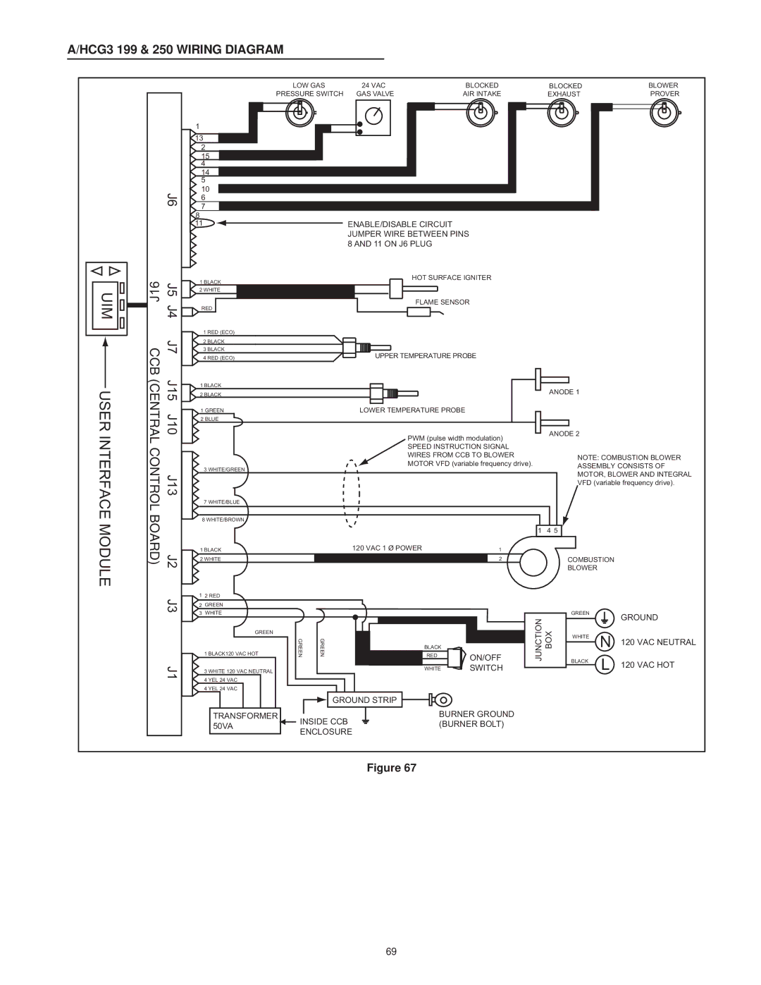
A/HCG3 199 & 250 WIRING DIAGRAM


J6

U

J16

J5

IM


J4


C

J7

USER INTERFACE MODULE

CB (CENTRAL CONTROL BOARD)

J15 J10 J13 J2

LOW GAS

24 VAC

BLOCKED

BLOCKED

BLOWER

PRESSURE SWITCH

GAS VALVE

AIR INTAKE

EXHAUST

PROVER

1


13


2


15


4


14


5


10


6


7


8

11 ENABLE/DISABLE CIRCUIT JUMPER WIRE BETWEEN PINS

8 AND 11 ON J6 PLUG


1 BLACK


HOT SURFACE IGNITER


2 WHITE


FLAME SENSOR


RED


1 RED (ECO)


2 BLACK


3 BLACK


UPPER TEMPERATURE PROBE


4 RED (ECO)


1 BLACK


2 BLACK


ANODE 1


1 GREEN


LOWER TEMPERATURE PROBE


2 BLUE


ANODE 2


PWM (pulse width modulation)


SPEED INSTRUCTION SIGNAL


WIRES FROM CCB TO BLOWER


NOTE: COMBUSTION BLOWER


MOTOR VFD (variable frequency drive).


3 WHITE/GREEN


ASSEMBLY CONSISTS OF


MOTOR, BLOWER AND INTEGRAL


VFD (variable frequency drive).


7 WHITE/BLUE


8 WHITE/BROWN


120 VAC 1 Ø POWER

1


1

4 5


1 BLACK


COMBUSTION


2 WHITE


2


BLOWER

J3

J1

12 RED

2 GREEN

3 WHITE

GREEN

1 BLACK120 VAC HOT

3 WHITE 120 VAC NEUTRAL

4 YEL 24 VAC

4 YEL 24 VAC

TRANSFORMER 50VA

RGEEN

RGEEN

BLACK


RED

ON/OFF


WHITE

SWITCH

GROUND STRIP

BURNER GROUND

INSIDE CCB (BURNER BOLT) ENCLOSURE

JUNCTION BOX

GREEN

WHITE

BLACK

N

L

GROUND

120 VAC NEUTRAL

120 VAC HOT

Figure 67

69

Page 69
Image 69
American Water Heater Commercial Gas Water Heaters instruction manual HCG3 199 & 250 Wiring Diagram, on J6 Plug

AHCG/HCG3 60T 120 - AHCG3/HCG3 100T 250, Commercial Gas Water Heaters specifications

American Water Heater's Commercial Gas Water Heaters, particularly the AHCG/HCG3 60T 120 and AHCG3/HCG3 100T 250 models, stand out in the market for their impressive performance and reliable efficiency. Designed to meet the demanding needs of commercial applications, these gas water heaters provide an optimal solution for businesses requiring consistent hot water supply.

One of the main features of the AHCG/HCG3 series is its exceptional heat capacity. The models are engineered to deliver high recovery rates, ensuring that adequate hot water is available even during peak demand periods. The AHCG/HCG3 60T 120 can yield a robust output, ideal for smaller to medium-sized facilities, while the AHCG3/HCG3 100T 250 is designed for larger operations that require enhanced capacity.

These water heaters incorporate innovative technologies to maximize efficiency. The use of a high-efficiency burner system significantly reduces gas consumption, earning these models an Energy Factor rating that complies with modern energy standards. Additionally, the inclusion of a direct vent design allows for safe and efficient exhaust management, further promoting the energy-saving capabilities of these units.

The design of these commercial water heaters prioritizes durability and longevity. Constructed with heavy-duty components, including a corrosion-resistant water tank, these models are built to last, reducing the need for frequent replacements and maintenance. They also feature an advanced control system that monitors and adjusts the operation for optimal performance, enhancing user experience while decreasing operational costs.

Another notable characteristic of the AHCG/HCG3 series is their flexibility in installation. Both the 60T 120 and the 100T 250 models offer various venting options, which means they can easily fit into the existing infrastructure of many commercial facilities. This versatility facilitates a seamless integration process, saving time and resources during installation.

With a commitment to providing effective hot water solutions, American Water Heater continues to innovate, making the AHCG/HCG3 series a valuable addition to any commercial establishment. From restaurants to laundromats and beyond, these gas water heaters deliver reliable performance, ensuring that businesses can operate smoothly and efficiently.