Configuration and Installation
Setting the Internal Jumpers (E1 and E2) for AXlink or
Internal jumpers are located on the circuit card inside the
Static electricity can damage electronic circuitry. Before removing the
Removing the circuit card
1.Discharge the static electricity from your body and the screwdriver.
2.Unplug all connectors from the rear panel of the
3.Remove the two
4.Remove the front or rear panel, and slide the circuit card out of the enclosure.
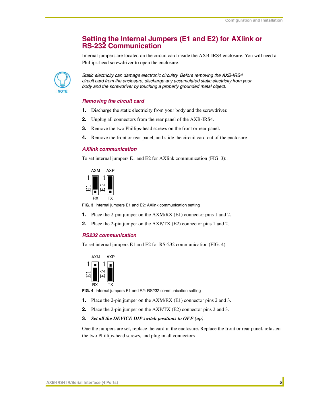
AXlink communication
To set internal jumpers E1 and E2 for AXlink communication (FIG. 3):.
AXM AXP
RX TX
FIG. 3 Internal jumpers E1 and E2: AXlink communication setting
1.Place the
2.Place the
RS232 communication
To set internal jumpers E1 and E2 for
AXM AXP
RX TX
FIG. 4 Internal jumpers E1 and E2: RS232 communication setting
1.Place the
2.Place the
3.Set all the DEVICE DIP switch positions to OFF (up).
One the jumpers are set, replace the card in the enclosure. Replace the front or rear panel, refasten the two
5 |
| |
|
|
|
