Installation and Wiring
JI jumper settings: TV power sensing/TV power current sensing mode
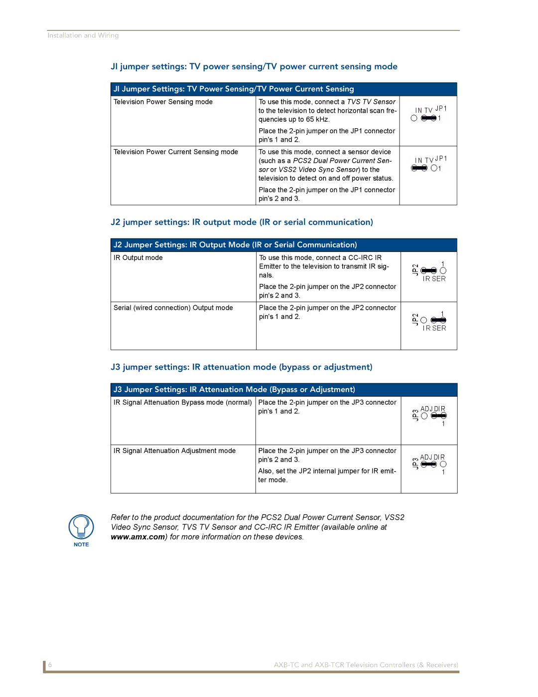
JI Jumper Settings: TV Power Sensing/TV Power Current Sensing
Television Power Sensing mode | To use this mode, connect a TVS TV Sensor |
|
| to the television to detect horizontal scan fre- |
|
| quencies up to 65 kHz. |
|
| Place the |
|
| pin's 1 and 2. |
|
|
|
|
Television Power Current Sensing mode | To use this mode, connect a sensor device |
|
| (such as a PCS2 Dual Power Current Sen- |
|
| sor or VSS2 Video Sync Sensor) to the |
|
| television to detect on and off power status. |
|
| Place the |
|
| pin's 2 and 3. |
|
|
|
|
J2 jumper settings: IR output mode (IR or serial communication)
J2 Jumper Settings: IR Output Mode (IR or Serial Communication)
IR Output mode | To use this mode, connect a |
|
| Emitter to the television to transmit IR sig- |
|
| nals. |
|
| Place the |
|
| pin's 2 and 3. |
|
|
|
|
Serial (wired connection) Output mode | Place the |
|
| pin's 1 and 2. |
|
|
|
|
J3 jumper settings: IR attenuation mode (bypass or adjustment)
J3 Jumper Settings: IR Attenuation Mode (Bypass or Adjustment)
IR Signal Attenuation Bypass mode (normal) | Place the |
|
| pin's 1 and 2. |
|
|
|
|
IR Signal Attenuation Adjustment mode | Place the |
|
| pin's 2 and 3. |
|
| Also, set the JP2 internal jumper for IR emit- |
|
| ter mode. |
|
|
|
|
Refer to the product documentation for the PCS2 Dual Power Current Sensor, VSS2
Video Sync Sensor, TVS TV Sensor and
www.amx.com) for more information on these devices.
6 |
|